
Installation Guide for Compac Liquid Fuel Pumps
Updated 18 March, 2026
Conditions of Use
Read this manual completely before working on, or making adjustments to, the Compac equipment
Compac Industries Limited accepts no liability for personal injury or property damage resulting from working on or adjusting the equipment incorrectly or without authorization.
Along with any warnings, instructions, and procedures in this manual, you should also observe any other common sense procedures that are generally applicable to equipment of this type.
Failure to comply with any warnings, instructions, procedures, or any other common sense procedures may result in injury, equipment damage, property damage, or poor performance of the Compac equipment
The major hazard involved with operating the Compac C5000 processor is electrical shock. This hazard can be avoided if you adhere to the procedures in this manual and exercise all due care.
Compac Industries Limited accepts no liability for direct, indirect, incidental, special, or consequential damages resulting from failure to follow any warnings, instructions, and procedures in this manual, or any other common sense procedures generally applicable to equipment of this type. The foregoing limitation extends to damages to person or property caused by the Compac C5000 processor, or damages resulting from the inability to use the Compac C5000 processor, including loss of profits, loss of products, loss of power supply, the cost of arranging an alternative power supply, and loss of time, whether incurred by the user or their employees, the installer, the commissioner, a service technician, or any third party.
Compac Industries Limited reserves the right to change the specifications of its products or the information in this manual without necessarily notifying its users.
Variations in installation and operating conditions may affect the Compac C5000 processor's performance. Compac Industries Limited has no control over each installation's unique operating environment. Hence, Compac Industries Limited makes no representations or warranties concerning the performance of the Compac C5000 processor under the actual operating conditions prevailing at the installation. A technical expert of your choosing should validate all operating parameters for each application.
Compac Industries Limited has made every effort to explain all servicing procedures, warnings, and safety precautions as clearly and completely as possible. However, due to the range of operating environments, it is not possible to anticipate every issue that may arise. This manual is intended to provide general guidance. For specific guidance and technical support, contact your authorised Compac supplier, using the contact details in the Product Identification section.
Only parts supplied by or approved by Compac may be used and no unauthorised modifications to the hardware of software may be made. The use of non-approved parts or modifications will void all warranties and approvals. The use of non-approved parts or modifications may also constitute a safety hazard.
Information in this manual shall not be deemed a warranty, representation, or guarantee. For warranty provisions applicable to the Compac C5000 processor, please refer to the warranty provided by the supplier.
Unless otherwise noted, references to brand names, product names, or trademarks constitute the intellectual property of the owner thereof. Subject to your right to use the Compac C5000 processor, Compac does not convey any right, title, or interest in its intellectual property, including and without limitation, its patents, copyrights, and know-how.
Every effort has been made to ensure the accuracy of this document. However, it may contain technical inaccuracies or typographical errors. Compac Industries Limited assumes no responsibility for and disclaims all liability of such inaccuracies, errors, or omissions in this publication.
Validity
Compac Industries Limited reserves the right to revise or change product specifications at any time.
This publication describes the state of the product at the time of publication and may not reflect the product at all times in the past or in the future.
Manufactured by:
Compac Laser and Master Pumps are designed and manufactured by Compac Industries Limited
52 Walls Road, Penrose, Auckland 1061, New Zealand
P.O. Box 12-417, Penrose, Auckland 1641, New Zealand
Phone: + 64 9 579 2094
Fax: + 64 9 579 0635
Email: techsupport@compac.co.nz
www.compac.co.nz
Copyright ©2015 Compac Industries Limited, All Rights Reserved
Overview of the steps required to instal a Compac Pmup
These are the basic steps to installing and commissioning a Compac Pump
For more detailed information, please refer to the C5000 Master Manual.
Identify the model that you are installing. This is stamped on the side of the unit.
Download the correct footprint
Calibrate the Pump and adust the K Factor if required
Set the Pump Number
Set the Price. Important: If connected to Controller, ensure that the correct price is being sent down to the Dispenser
If connected to a Controller, set the Standalone b setting as required.
Product Identification
Ensure you are using the correct installation instructions and footprint drawing before commencing site work or installation.
The identification plate is fastened to the bottom of the right-hand side panel when facing the front of the dispenser.
The model number is on the first line of the identification plate.
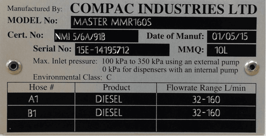
Understanding the model number:
The model number for Pumps and Dispensers is split into: Chassis style, hose configuration, pump or dispenser and specific application.
Use the table below to help identify the unit.
The same format applies to both Laser and Master models
The following example is for the Master Pump or Dispenser
Style | L/min oer hose | Pump style | Options |
|---|---|---|---|
MR=single hose | MR40 = one hose @ 40l/min | P = Pump | Blank = standard |
MMR=multi hose | MMR40=two hoses @ 40 l/min | S = Dispenser | Avi = Aviation |
MMR80-40 = side A 80 lpm, side B = 40 lpm | Marine = Marine |
For example: MMR 80-40S Marine is a two-hose unit.
Hose side A is 80 l/min, side B is 40 l/min with external pumps.
As a marine model, it has stainless steel pipework and stainless-steel chassis for marine conditions.
Footprints
All outlets are approximately 680mm above the base: Outlet sizes are as follows:
40 l/min - ¾” female BSP socket
80 l/min - 1” female BSP socket
160 l/min - 1 ¼” female BSP socket
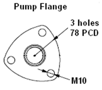
Inlet pipework can be connected to the pump flange(s).
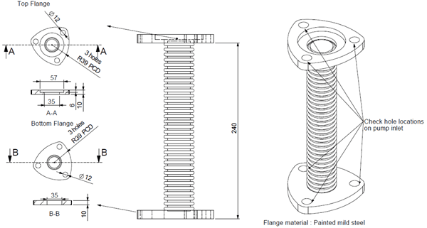
An optional flexible coupling is offered by Compac. There must be no fuel pressure in the pump line when pump is not operating.
Optional Inlet Flexi Coupling
Static Electricity Precautions
Electronic components used are sensitive to static. Please take anti-static precautions.
An anti-static wrist strap should be worn and connected correctly when working on any electronic equipment. If an anti-static wrist strap is unavailable, or in an emergency, hold onto an earthed part of the pump/dispenser frame whilst working on the equipment. This is not a recommended alternative to wearing an anti-static wrist strap.
NOTE: Compac Industries Limited reserves the right to refuse to accept any circuit boards returned, if proper anti-static precautions have not been taken.
Pre-installation Check
Once the pump is received on site, check that no damage has occurred while in transit – in particular, damage to electronics due to vibration or jarring.
All terminals and plugs should be checked, including IC chips, to ensure they are securely in place.
Installation requirments for Pumps
To obtain maximum flow on a self-contained pump, observe the following guidelines:
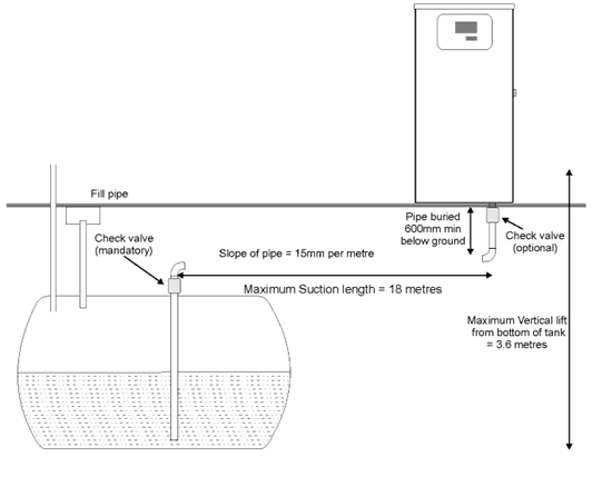
Below Ground Tank Installations
Pumps must not be subject to any head pressure. Design your installation to eliminate any possibility of this occurring.
Total length of horizontal piping between tank and pump should be no longer than 18 metres.
Use galvanised steel or approved non-metallic pipe and fittings.If the unit contains two pumps. It is recommended that each pump is supplied by a separate pipe. The common sizes used are.
• 40 l/min pumps, use a separate1½” pipe for each pump
• 80 l/min pumps, use a separate 2” pipe for each pump
• 160 l/min, single hose pumps, use either a separate 2” pipe for each pump, or, a single 3” pipe.
Important Note: Do not feed two pumps from a single 2” pipe. This will result in the Pumps cavitating
4. Check valves must also be installed below each pump inlet.
On 160lpm units, if a single 3" Suction line is used, Check valves must be fitted to the inlets of both pumps to prevent one pump drawing product back through the other.
Important Note:
Ensure that you remove the bung from the pump inlet before connecting the pipe.
If the bung is not removed, there wil be no product flow.
Pipe must slope up from the tank to the pump (approximately 15 mm per metre). Pipe should be straight and supported along its length.
All horizontal piping must be buried at least 450mm below ground level.
The area under the pumping unit(s) must be filled with sand or dirt as far up the suction line as possible. Use water to pack the sand or dirt when put in place.
Avoid asphalt drive surfaces covering the piping. Asphalt increases heat absorption causing vapour lock.
Static lift must not exceed 3 metres (vertical distance from the product level in the tank to the centre of the pump unit).
To absorb ground movement from settling of the tank, frost heaving of the ground or pump island settling, a swing joint must be used in the supply line at the tank and directly underneath the dispenser. Three additional directional changes using elbows are permitted.
Piping must hold a 3.4 Bar (50PSI) pressure test for a minimum of 10 minutes.
It is recommended that a vertical, in-line check valve be installed underneath the pump.
The dispensing equipment shall be installed to prevent the delivery hose from contacting the ground when not in use.
A check valve must be installed at the tank end of the suction pipe in a serviceable location. Many clients install an extra check valve at the inlet to the pump. It is important neither of the check valves interfere with the flow of fuel. They must be adequately sized.
Refer to the footprint drawings for pump installation details.
Above Ground Tank Installations
If a regulator valve is not installed correctly, product will pour out of the pump breather. If this happens do not plug the breather.
Review the installation and ensure that all the following requirements have been met.
The regulator valve must be mounted in the vertical position and directly underneath the pump. Do not mount alongside the pump as no pipework between the regulator valve and the pump is allowed to be below the regulator valve itself.
Do not plug the vent on the regulator valve. Pipe the vent back to the top of the tank or vent to atmosphere.
Maximum working pressure of fuel system = 50 psi / 3.4 bar
The installation must include a thermal expansion relief valve. Thermal expansion can cause pressures in the system greater than 50 psi / 3.4 bar and can result in failure of the valve and loss of product to the environment.
The installation must also include a solenoid valve positioned adjacent to the shut off valve at the tank. Its purpose is to prevent loss due to failure of the downstream piping or the system. The recommended solenoid is the Parker 2" type E321G4010 (available from Compac)
The Shear section of the regulator valve should be located level with the bottom of the cabinet base.
The installation must include a shutoff or gate valve to close the system and prevent loss when the equipment utilized in the fuelling system downstream from the above ground storage tank is being serviced or replaced.
Dispensing Hoses and Nozzles
The unit may or may not be supplied with dispensing hose and nozzle assemblies.
If customer supplied hose assemblies, pylons, reels, safe breaks and nozzles are used they must comply with the requirements outlined in AS/NZS 2229.
All dispenser nozzles must trip shut when returned to the nozzle holder.
Breakaways
For all pumps that are fitted with breakaways, ensure that the breakaway is installed between the nozzle and the high-mast or pylon (if fitted).
Any breakaways that have been subject to a break-away situation should be inspected and refitted or replaced in accordance with the original manufacturer’s instructions.
Typical Wiring for a Pump
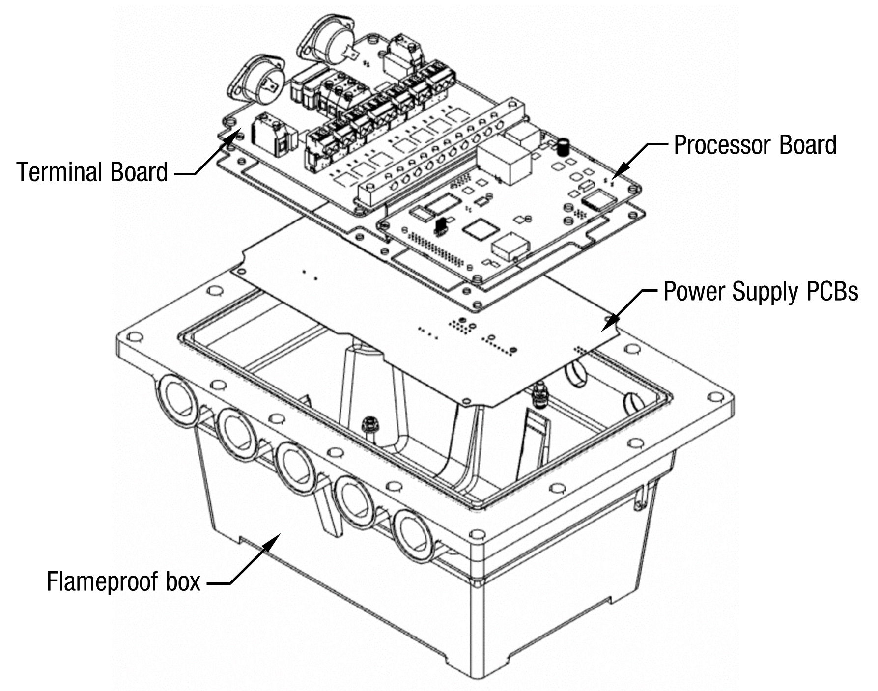
The instructions below refer to basic installation wiring. Prior to pump installation ensure that there is at least a two-metre tail on both the incoming underground mains supply cable and comms cable (if comms enabled). These cables are terminated at the C5000 power supply, which is housed in the flameproof enclosure located in the bottom of the pump, behind the door.
Mains power wiring should be rated for a maximum current draw of 10 A rms at 220-240 V ac.
The incoming cables are terminated as shown in the following picture.
Refer to AS/NZS 60079.14 for appropriate cabling.
NOTE: All cables entering the power supply must be glanded with certified 20mm flameproof glands.
NOTE: Comms cable is not intrinsically safe.
NOTE: Pump comms connects to pump controller such as a PT1, Comfill V2 or thord Party Controller etc. (option).
When replacing the lid of the flameproof enclosure, ensure the sealing O ring is in place.
Incoming Mains
Incoming mains connections should be brought in to the terminal board.
If an emergency stop button was ordered with the pump, it will be factory wired into the
terminal board, shown below.
This will be in place of the normal loop between the triac and
main phases.
If there is an Overfill Protection System (either Compac or Third Party), it should be wired as an Emergency Stop Switch would be between the Triac Phase and Mains Phase
If there is both an Emergency Stop Switch and an Overfill Protection System, they should be wired in series so that either can interupt the Triac Phase in cas of an emergency
Wires have standard colours which are shown. In case these colours are unclear, they are as
follows:
▪ Incoming mains phase: Brown
▪ Incoming mains neutral: Blue
▪ Incoming mains earth: Green/Yellow

Comms connections
The comms I/O is controlled by the connections to the CI501 Comms board which is piggy backed on the Power Supply inside the flame-proof enclosure.
Refer to the following diagram for connecting RS485, RS232, Compac or Gilbarco pumps. The shown switch should be set to the desired setting.
NOTE Ensure that SW200 (Switch 1) is set the required protocol
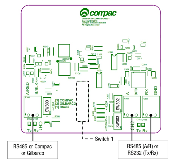
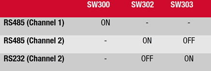
Switches 300, 302, and 303 are for RS485/RS232 Terminator application.
Use the following table to configure these switches. Switch 300 is for channel 1, and switches 302 and 303 are for channel 2.
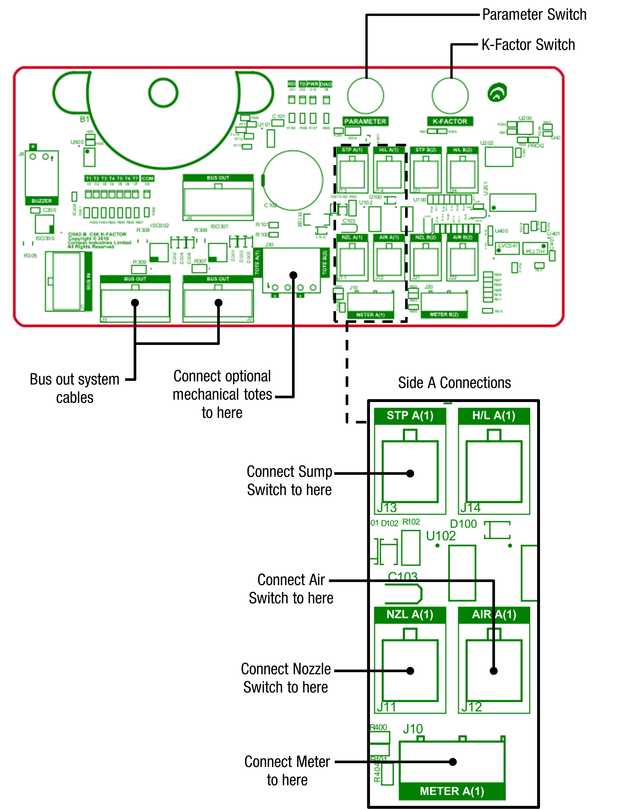
K-Factor Board
Both the Parameter switch and K-Factor switch are found on the K-Factor board. Meters and air switches are also connected to this board. See below for the location of these.
Setting up the C5000
K-Factor Settings
The settings that can be accessed from the K-Factor switch are shown below. Not all of these will need to be changed during installation, therefore information on the following pages refers only to the settings that must be changed. Once the Dispenser has been installed, if further customisation of the unit is required, refer to the C5000 Master Manual.
Setting | Price Display | Litres Display | Important notes | |
|---|---|---|---|---|
Dispenser settings | c-A or c-B | ******* | These are set in the factory and should not be changed | |
Maximum flow | 9A**** or 9b **** | |||
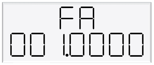
K-Factor | FA or Fb | ***.*** | ||
Configuration code | c | ******* | This is set in the factory and should not be changed | |
Preset cutoff | PcA*.** or Pcb*.** | This is available if a secondary solenoid is wired in | ||
Preset rounding | PrLA*.** or PrLb*.** PrHA*.** or PrHb*.** | |||
Flow time out | n-A *** or n-b *** |
Changing the K factor FA and Fb
The K-Factor is used to calibrate product flow. It is a ratio of litres dispensed per revolution of the meter. The K-Factor may need to be calibrated after periods of time.
To calibrate the pump, dispense fuel into a certified measuring container and compare the display value with the one dispensed.
Example:
The Display shows 10.00 litres but the True volume is actually 20.00 Litres
To calculate the correct K-Factor from the information above; firstly record the existing K-Factor and use this formula to calculate the new K Factor.
New K Factor=Existing K Factor x (Dispensed Amount)/(Displayed Amount)
=Existing K Factor x 20/10
=Existing K Factor x 2
See Using the Dispenser Menus to edit these settings. Use the procedure for both side A and B.
5 Parameter Switch Settings
The settings that can be accessed from the parameter switch are shown below.
Not all of these will need to be changed during installation, therefore information on the following pages refers only to the settings that must be changed.
Once the pump has been installed, if further customisation of the unit is required, refer to the C5000 Master Manual.
Setting | Price Display | Litres Display |
|---|---|---|
Software Version | P**.**. ** | P**.**. ** |
Pump Number | PnA *** or PnB *** | |
Price | PA**.*** or Pb**.*** | |
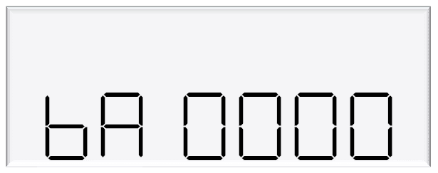
Pump Settings | ba **** or bb **** | |
High Preset cut off | HCA** or HCb** | |
High-flow cut off | HFA*** | |
Low-flow cut off | LFA*** | |
b Setting | b**** | |
Slave display | d5 **** | |
Custom display | dc **** | |
Last Sale | . | A***.* or b***.* |
Electronic Totes | LA **** or dA**** | L****.** |
Lb **** or db**** | d****.** |
Changing the Pump Number
If the parameter switch is continually depressed, the following menu to change the pump number will appear.
Each side must be numbered between 1-99. Entering a pump number 0 will disable the pump.
To change the pump number, depress the parameter switch repeatedly until the following display is shown.
To increment a digit, press and hold the parameter switch when the desired digit is flashing. Repeat this procedure for side B if applicable.

Changing the Price
The price must be set before the dispenser can be used, otherwise an error will be returned. Set the price in dollars per litre.
To change the price, depress the parameter switch repeatedly until the following display is shown. To increment a digit, press and hold the parameter switch when the desired digit is flashing. Repeat this procedure for side B if applicable.

Standalone Mode
In standalone operation, the dispenser will continue working when not connected to a controller. When in Standalone mode no authorisation of fills is required and so fills are simply initiated by removing the refuelling assembly from its holder. If standalone operation is inhibited, the dispenser will not work in standalone mode, regardless of whether the dispenser is ONLINE to a controller or not.
The dispenser ceases to work in standalone mode if connected to a controller, regardless of the position of standalone setting.
Generally, on retail forecourts the dispenser should be set-up for standalone operation. Hence, if the forecourt controller breaks down the dispensers can be set to work in standalone mode simply by turning them off then on again.
For unattended refuelling sites, the dispensers should not be able to work in standalone mode in the event of a controller failure. Therefore, the dispenser should be set-up to inhibit standalone operation.
This is set in the b code on the K factor switch. The b code to run Standalone without Dispenser Controller is 1000. The b code to inhibit Standalone is 0000.
Notes
Pump Controller
If the pump is connected to a controller, check that pump data and transaction information is being correctly uploaded to it.
Refer to the controller manual for specific instructions regarding connection and setup.
Spare Fuses
In the event of a fuse blowing on the C5000 Power supply a bag of 3 is included in each flameproof box. Any fuses used from this bag should be replaced.
NOTE: There are three different ratings used. If replacing a fuse, ensure that the correct value is used.
Precautions if Using Generator Power
The power output from onsite generators can cause power spikes that may damage electrical components within the cabinet. When connecting to sites powered by generators, please take the following precautions:
Install a power conditioner. Although generators are fitted with power regulators, most are not filtered sufficiently for powering sensitive electrical components. We recommend installing a commercial power conditioner and/or UPS between the generator and the unit.
Before starting a generator, make sure the power to the unit is turned off. Start the generator, let the generator reach stable operating speed and wait 30 seconds before reconnecting the power to the unit.
For units where the generator starts and stops on demand, install a delay timer or PLC to automatically isolate the unit until the operating speed and consistent power output is achieved.
Isolate the unit before shutting down the generator.