
C5000 Master Manual
Specifications
Models Covered
Note: Do not use this manual for earlier models. Contact Compac for archived manuals if required.
Validity
Compac Industries Limited reserves the right to revise or change product specifications at any time. This publication describes the state of the product at the time of publication and may not reflect the product at all times in the past or in the future.
Manufactured By
The Compac C5000 is designed and manufactured by Compac Industries Limited
52 Walls Road, Penrose, Auckland 1061, New Zealand
P.O. Box 12-417, Penrose, Auckland 1641, New Zealand
Phone: + 64 9 579 2094
Email: techsupport@compac.co.nz
Website: http://www.compac.co.nz
Copyright ©2015 Compac Industries Limited, All Rights Reserved
Document Control
Document Information
Manual Title: C5000 Master Manual
Current Revision Author(s): Trevor Watt
Original Publication Date: 20 September 2021
Last updated: 4 March 2026
Authorised By: Emily Sione
File Name: C5000 Master Manual
Conditions of Use
Read this manual completely before working on, or making adjustments to, Compac equipment
Compac Industries Limited accepts no liability for personal injury or property damage resulting from working on or adjusting the equipment incorrectly or without authorization.
Along with any warnings, instructions, and procedures in this manual, you should also observe any other common sense procedures that are generally applicable to equipment of this type.
Failure to comply with any warnings, instructions, procedures, or any other common sense procedures may result in injury, equipment damage, property damage, or poor performance of the Compac equipment
The major hazard involved with operating the Compac C5K processor is electrical shock. This hazard can be avoided if you adhere to the procedures in this manual and exercise all due care.
Compac Industries Limited accepts no liability for direct, indirect, incidental, special, or consequential damages resulting from failure to follow any warnings, instructions, and procedures in this manual, or any other common sense procedures generally applicable to equipment of this type. The foregoing limitation extends to damages to person or property caused by the Compac C5K processor, or damages resulting from the inability to use the Compac C5K processor, including loss of profits, loss of products, loss of power supply, the cost of arranging an alternative power supply, and loss of time, whether incurred by the user or their employees, the installer, the commissioner, a service technician, or any third party.
Compac Industries Limited reserves the right to change the specifications of its products or the information in this manual without necessarily notifying its users.
Variations in installation and operating conditions may affect the Compac C5K processor's performance. Compac Industries Limited has no control over each installation's unique operating environment. Hence, Compac Industries Limited makes no representations or warranties concerning the performance of the Compac C5K processor under the actual operating conditions prevailing at the installation. A technical expert of your choosing should validate all operating parameters for each application.
Compac Industries Limited has made every effort to explain all servicing procedures, warnings, and safety precautions as clearly and completely as possible. However, due to the range of operating environments, it is not possible to anticipate every issue that may arise. This manual is intended to provide general guidance. For specific guidance and technical support, contact your authorised Compac supplier, using the contact details in the Product Identification section.
Only parts supplied by or approved by Compac may be used and no unauthorised modifications to the hardware of software may be made. The use of non-approved parts or modifications will void all warranties and approvals. The use of non-approved parts or modifications may also constitute a safety hazard.
Information in this manual shall not be deemed a warranty, representation, or guarantee. For warranty provisions applicable to the Compac C5K processor, please refer to the warranty provided by the supplier.
Unless otherwise noted, references to brand names, product names, or trademarks constitute the intellectual property of the owner thereof. Subject to your right to use the Compac C5K processor, Compac does not convey any right, title, or interest in its intellectual property, including and without limitation, its patents, copyrights, and know-how.
Every effort has been made to ensure the accuracy of this document. However, it may contain technical inaccuracies or typographical errors. Compac Industries Limited assumes no responsibility for and disclaims all liability of such inaccuracies, errors, or omissions in this publication.
Table of Contents
1 Safety
2 Electrical Installation
C5000 Power Supply 230v Mains connections
Cable and Mains Power Requirements
K-Factor board
Typical wiring
3 COMMS connections and settings
3-1 COMPAC and PEC COMMS
3-2 GILBARCO COMMS
3-3 DART COMMS
4 K-Factor Switch settings
Changing the C-A and C-b Dispenser settings
Changing the V50 Meter ID
Changing the Temperature Calibration E-A and E-b
Changing the Density Calibration dIS-A
Changing the Maximum Flow rate 9A and 9b
Changing the K factor FA and Fb
Default K Factor setting
Changing Configuration C
Changing COMMS CC
5 Parameter Switch Settings
How to view the Software Version
Changing the pump number
Changing the price
Changing the Pump settings
Changing the High Preset Cut
Pump settings on Parameter switch explained
Changing the Low-flow Cutoff
Changing the High-flow Cutoff
Changing the b setting
Changing the Slave Display Configuration
Assigning a number to slave display
Changing the Custom Display Configuration
How to view the Last Sale
How to view Electronic Totes
Enabling Amount or Quantity Preset
Preset Board DIP Switch settings
GPIO board applications
1 GPIO board set up for Pulse Input from a Flow Meter
2 GPIO board set up in Input Switch mode
3 GPIO board set up in Pulse Output mode
Commissioning
Electrical
Mechanical
LED Diagnostics
C5K Processor Board
K Factor board
K Factor Board Output LEDs
Troubleshooting electrical problems
Electrical problems
Mechanical problems
Software upgrade
Generator Power
Error Codes
END OF SALE Indicators
1-0 Safety
PRECAUTIONS
Always follow safe operating procedures, any national or local regulations, and site-specific instructions.
Always turn the power off to the unit and properly isolate so power cannot be turned on by mistake.
Turn off isolating valves to the dispenser and drain the fuel before any mechanical servicing.
Electrical Safety
Observe the following electrical precautions:
Always turn off the power to the Compac C5000 processor before opening the flame-proof box.
Never touch wiring or components inside the high voltage area with the power on.
Always turn off the power to the Compac C5000 processor at the mains switch before removing or replacing software or memory ICs.
Always take basic anti-static precautions when working on the electronics, i.e., wearing a wristband with an earth strap.
Site Safety
Obey all company regulations and site-specific instructions relating to the installation.
Before working on any hydraulic equipment, drain the dispenser in an approved manner.
Static Electricity Precautions
Electronic components used are sensitive to static. Please take anti-static precautions.
All circuit boards must be carried and transported in static-shielded bags.
An anti-static wrist strap should be worn and connected correctly when working on any electronic equipment.
If an anti-static wrist strap is unavailable, or in an emergency, hold onto an earthed part of the pump/dispenser frame whilst working on the equipment. This is not a recommended alternative to wearing an anti-static wrist strap.
Compac Industries Limited reserves the right to refuse to accept any returned circuit boards if proper anti-static precautions have not been taken.
2 Electrical Installation
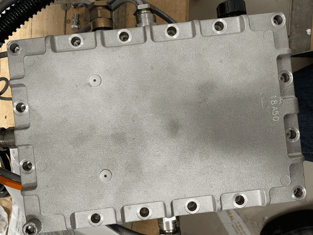
C5000 Power Supply
The C5000 may be supplied unmounted for use in applications such as controlling mechanical registers in a bulk dispensing area or mounted on a truck for mobile dispensing.
When installing the C5000 power supply, please observe the following instructions.
Cable Entries
There are fourteen cable entries:
Five along the top of each of the long sides
Three along one short side of the box
One at the bottom
All cable entries have an M20 thread.
The bottom cable entry is used for the power supply output cable.
The thirteen top cable entries are for power cable and communication connections.
Use only certified Ex 'd' glands and thread adaptors if required.
Blank all unused entries with certified M20 Ex 'd' blanking plugs.
Do not use thread adaptors with blanking plugs.
All cables must carry appropriate certification for the required application.
Area of Use
Correctly installed, the power supply is suitable for use in Zone 1 areas as defined in IEC 60079-14, group classification IIA, temperature classification T4, ambient temperature range -25°C to 55°C.
With the o-ring fitted in the base and the use of appropriate glands, the enclosure provides protection to IP66.
Location
Mount the power supply in a horizontal position, isolated from vibration and sheltered from excess water spray.
Failure to do this may void the warranty.
Installation
Fasten the power supply using the four M6 tapped holes in the base.
Hole centres: 185 mm x 105 mm
Minimum thread engagement: 9 mm
Maximum thread engagement: 14 mm
Wiring
Wiring must be carried out in accordance with the relevant code of practice.
All terminal wiring must have a cross section area of 0.5 mm² to 4 mm².
Wiring used should be suitable for 80°C.
Insulation must extend to within 1 mm of the metal face of the terminal.
Not more than one single or multi-stranded wire should be connected to the terminals unless they have been pre-joined in an appropriate manner.
Installation Procedure
Ensure the unit is isolated from the power source.
Remove the sixteen M10 x 20 stainless steel cap screws and remove the lid.
Feed all wires into the box via an appropriate gland and connect.
The Earth wire from the power lead must be earthed to the casing using a proper terminal.
Replace the lid making sure the gasket is in place and clean and that no wires have been pinched.
External Earthing
Where required, earth the C5000 Power Supply using an earth wire with a cross-sectional area at least equal to the largest conductor.
The earth wire is attached to the integrated point.
Cable and Mains Power Requirements
Cable Requirements
Power
Cable Type: 3 Core Steel Wire Armour Cable, 2.5 mm²
Voltage: 220–240 V, 50 Hz, ±10%
Core Details:
Core 1: 230 V Supply (Active)
Core 2: Neutral
Core 3: Earth
Dispensers:
25 W idle
300 W with all solenoids active
Submersible Pump(s):
Suitable cable for 230 V solenoid switching current
300 mA maximum load
Do not wire submersible pumps directly to C5000 power supply.
Pumps
C5000 Power Label: 110–240 Vac, 50/60 Hz, 15 A
This rating caters for start-up current of two motors (e.g., MR160P).
Mains supply must support up to 15 A.
Actual usage:
2 × 750 W motors + 2 × dual solenoids (<30 W each) + electronics (<300 W)
Examples:
MR80P (1 × 750 W motor): <1.1 kW with motor and solenoid active
MR160P (2 × 750 W motors): <2 kW with both motors and solenoids active
Comms
Cable Type: 2 Core Steel Wire Armour Cable, 1.5 mm²
Max Length: 100 m
Voltage: 12 V current loop
Ensure at least 2 m cable tail for both incoming 230 V and comms cables to reach C5000 flameproof box.
If using generator power, refer to the Generator Power section.
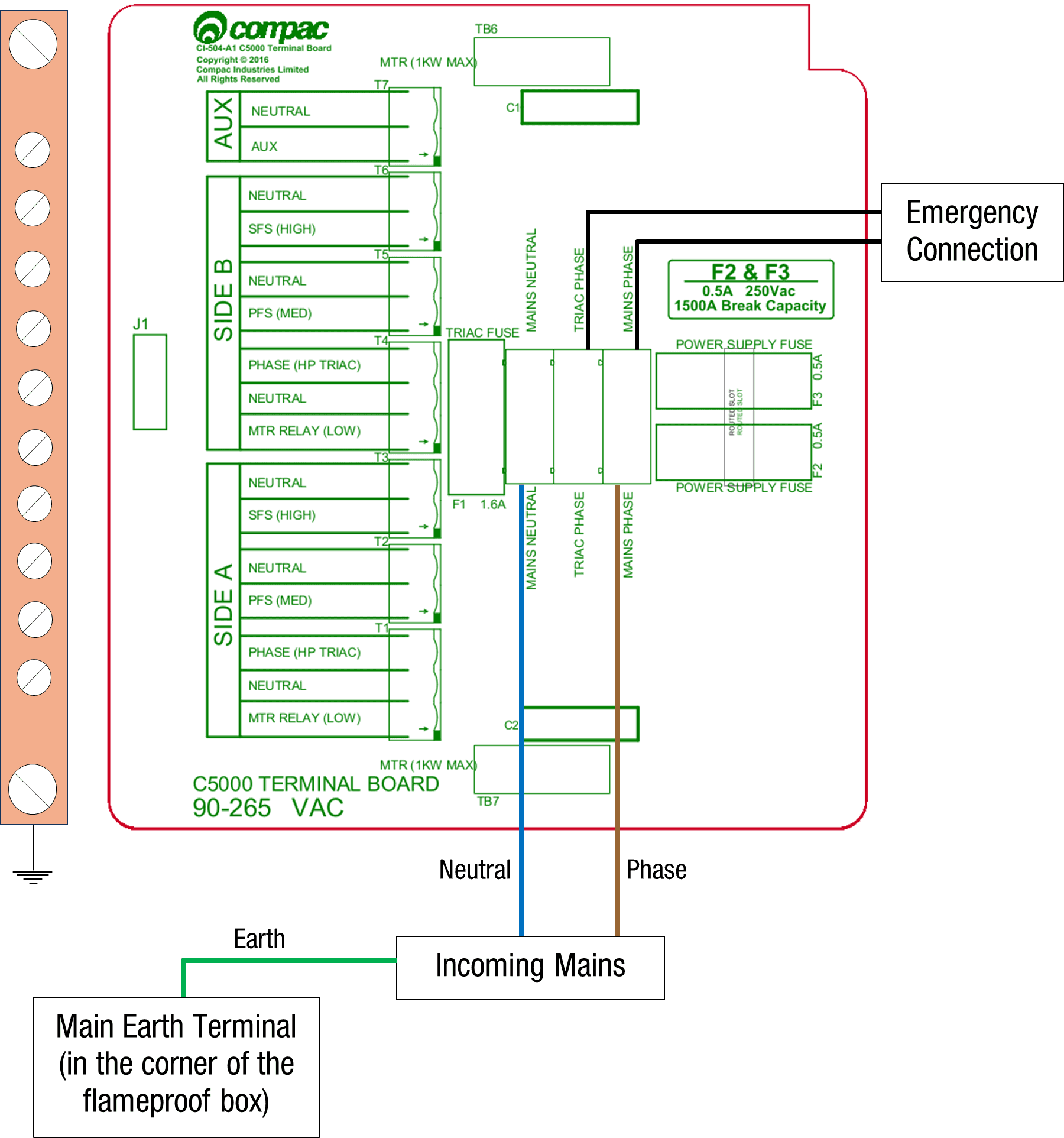
C5000 Power Supply 230v Mains connections
Connections should be brought into the terminal board.
Optional: Emergency stop connection can replace the normal loop between triac and main phases.
Wire Colours:
Incoming mains phase: Brown
Power Supply
The C5000 Power Supply is found within the flameproof box, located on the unit.
The Power Supply enclosure also contains the Processor board, Terminal board and Comms board
which are piggy-backed on top of the Power Supply.
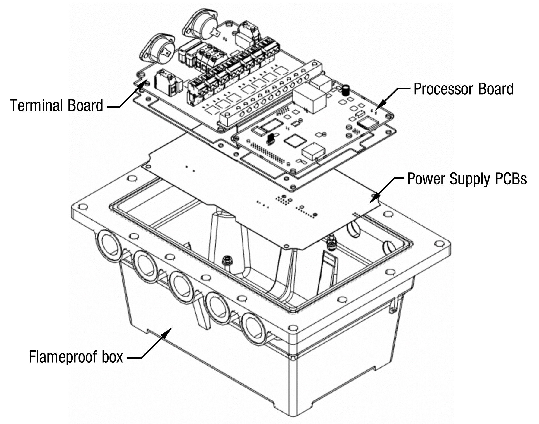
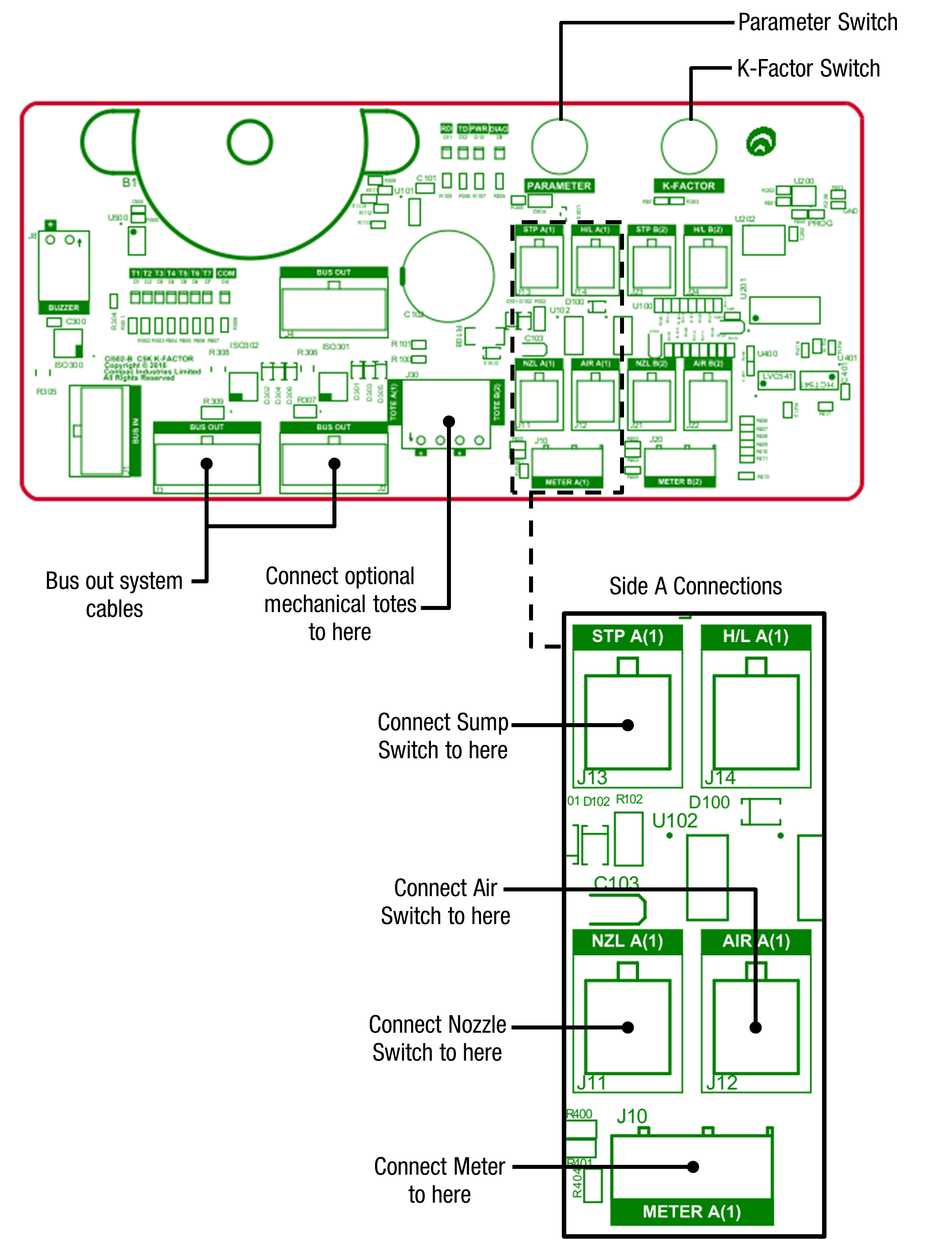
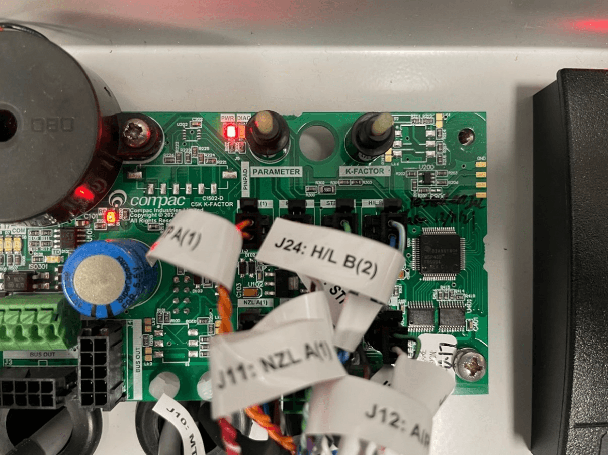
K-Factor board
Both the Parameter switch and K-Factor switches are located on the K-Factor board. Meters and air switches are also connected to this board. See below for the location of these.
Typical Wiring
Caution:
The following diagrams are typical only and will vary between different models.
Check the installation instructions for the exact model that you are working on
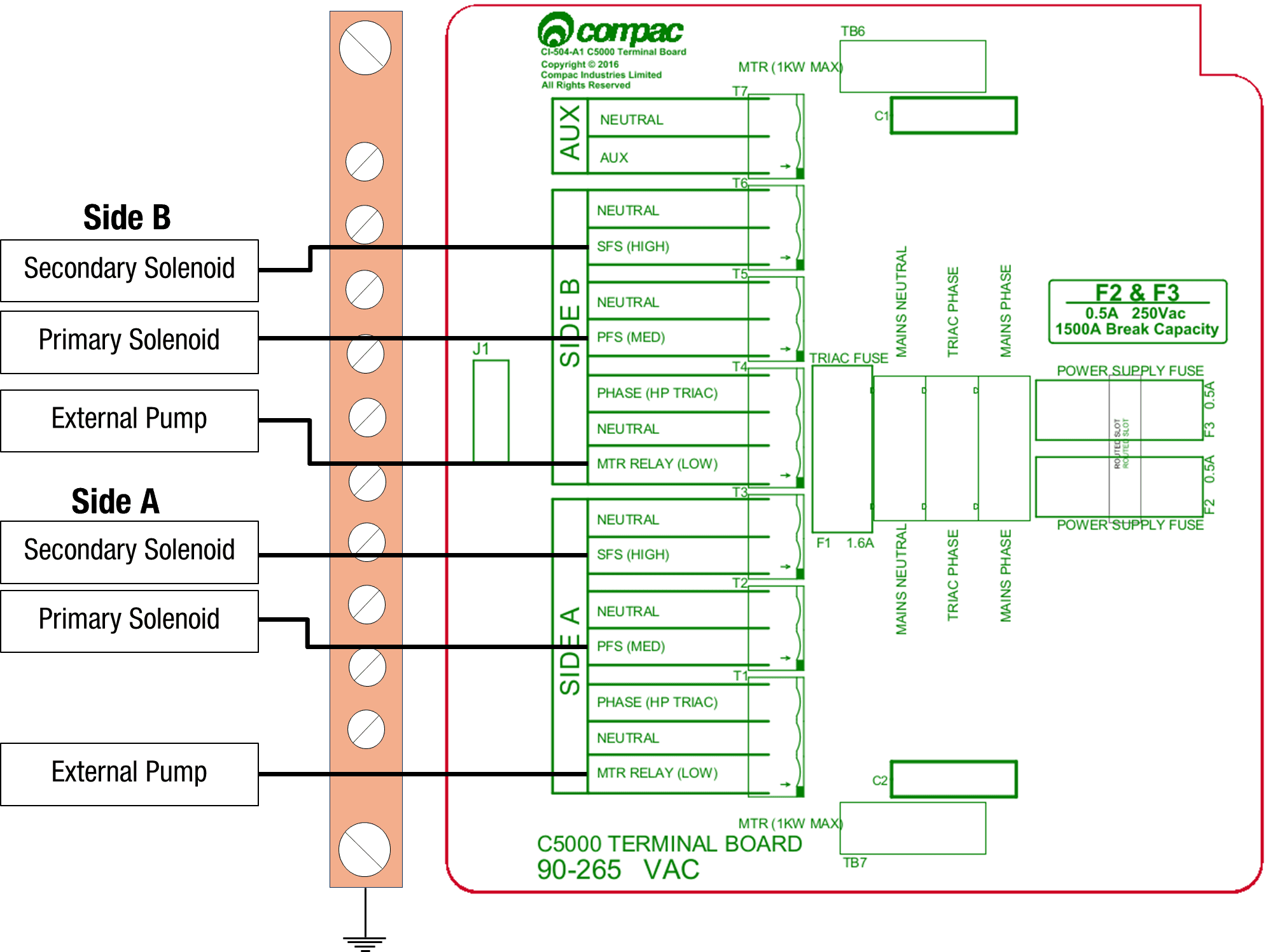
Pumps
The following diagrams show the typical wiring required for C5000 pumps.
The motor can be connected to the terminal board for both side A and side B. Only wire in the required side(s). The location of the fuses on the terminal board are also shown. These can be used for diagnosing problems with the unit.
Solenoids for side A and B are optional and can be wired in if preset and prepay options are desired.
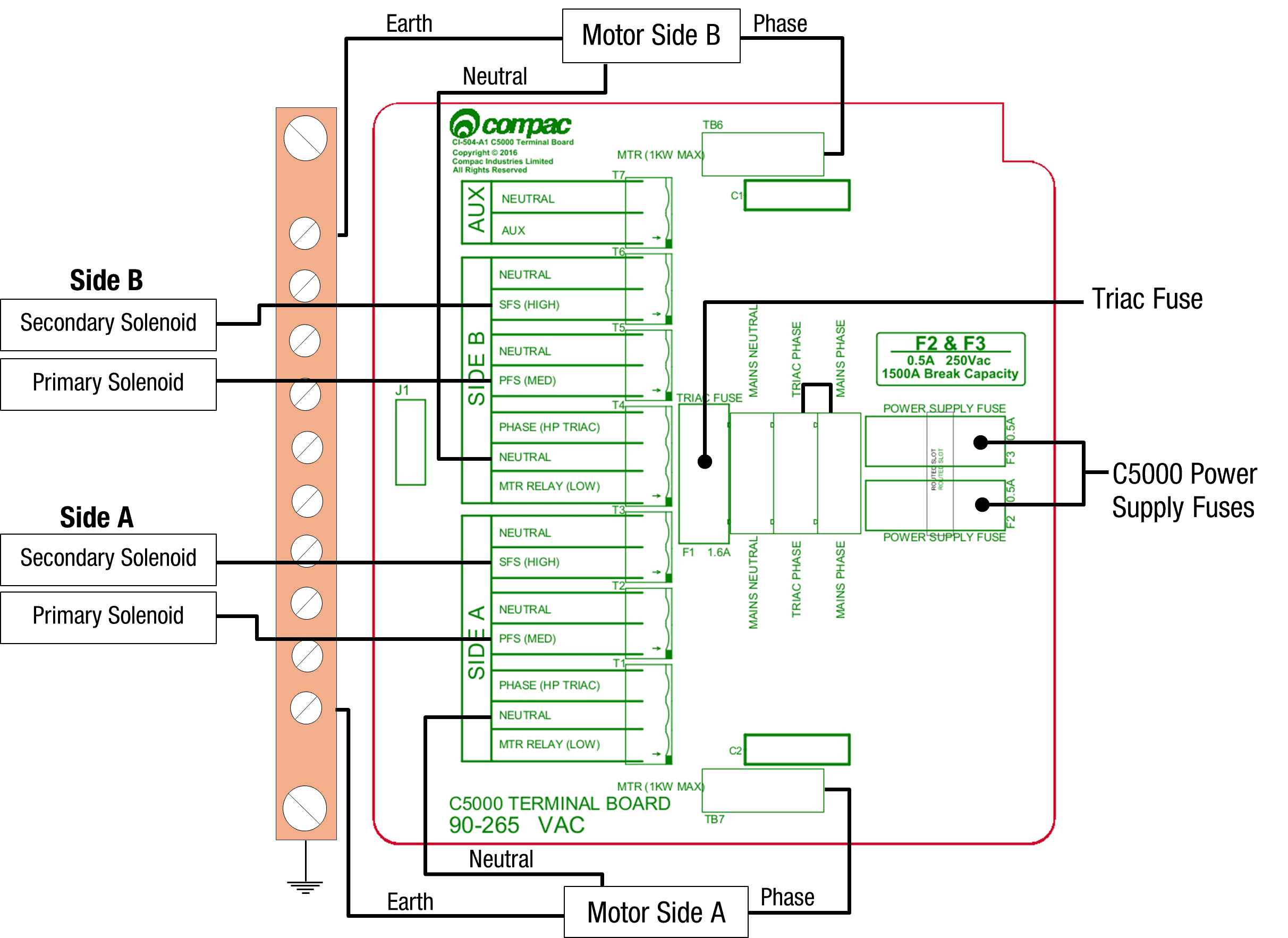
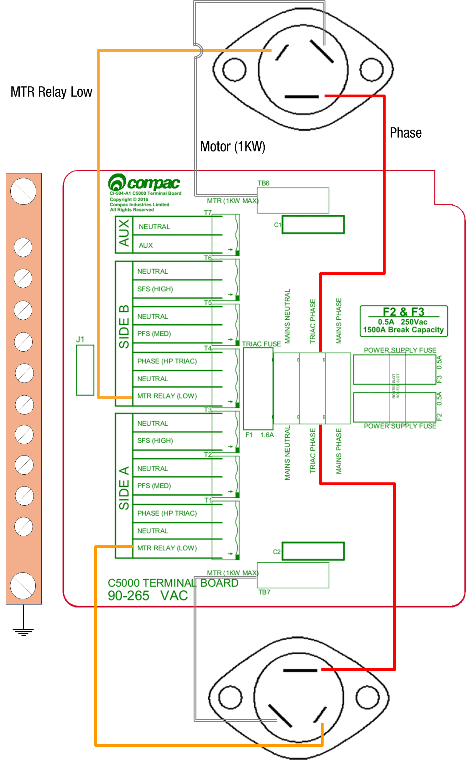
Triac Wiring
The triac wiring is pre-installed and, in most cases, will not need to be changed. However, the wiring is shown here to aid triac replacement or other service procedures. These are colour coded with standard colours. In case these are not clear, the colours are as follows:
MTR Relay: Orange
Phase: Red
Motor: White
Dispensers
When using the C5000 electronics for dispenser application, as well as connecting the incoming mains, the external pump contactors will have to be connected to the terminal board.
Solenoids for side A and B are optional and can be wired in if preset and prepay options are desired.
- Incoming mains neutral: Blue
Incoming mains earth: Green/Yellow
3 COMMS connections and settings
Important note:
There are two types of Comms Interface boards used in the C5000
CI501 - This is used in standard Pumps and Dispensers that are connected to either Compac or Third Party Contollers
CI533 - This is used when the C5K is acting as the controller such as in PT1, ComfillV2 and Fillmaster
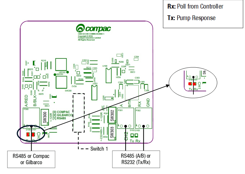
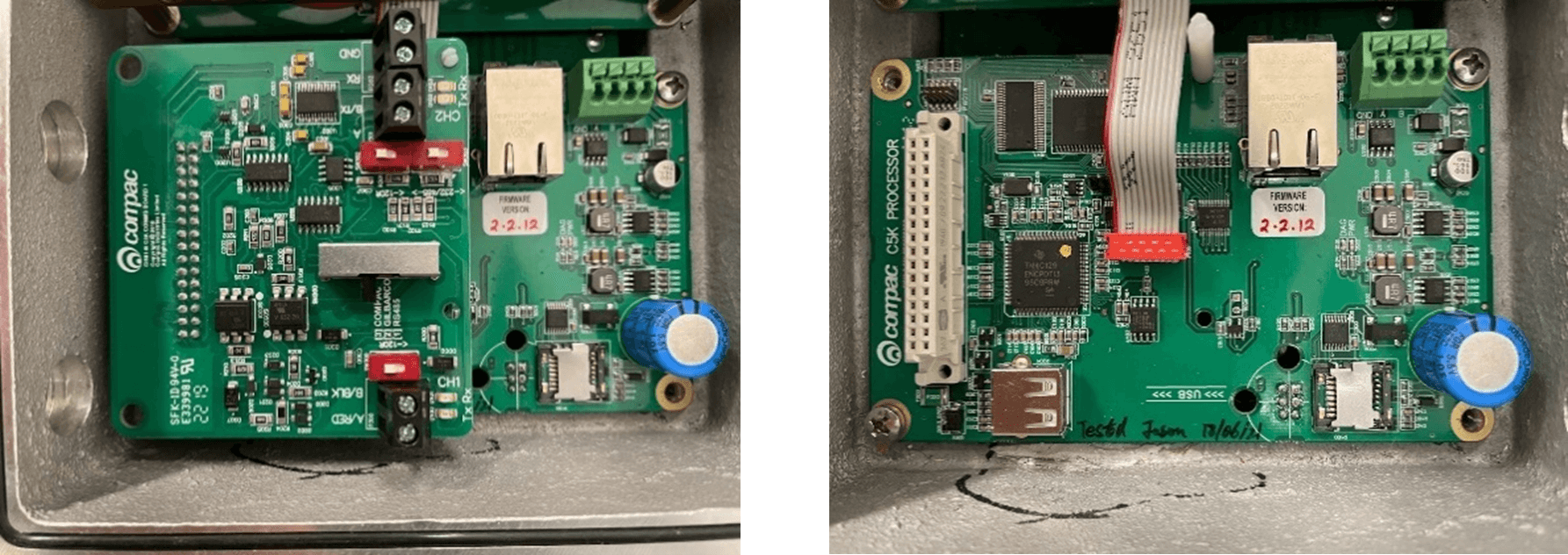
CI501 Comms Board
The comms I/O is controlled by the connections to the Comms board. Refer to the following diagram for connecting RS485, RS232, Compac or Gilbarco pumps. The shown switch should be set to the desired setting.
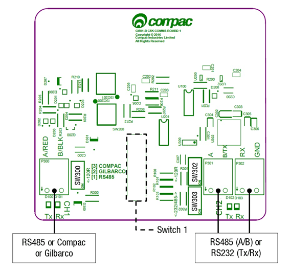
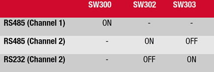
Switches 300, 302, and 303 are for RS485/RS232 Terminator application.
Use the following table to configure these switches. Switch 300 is for channel 1, and switches 302 and 303 are for channel 2.
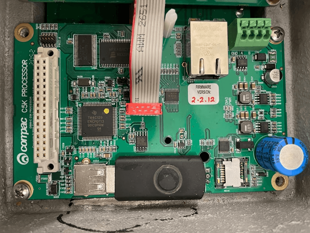
CI533 Comms board
In C5000 Compac Pumps and Dispensers, the CI533 Comms interface PCB board is piggy-backed on top of the Processor Board
In a COMFILL or PT1, A 15 core multicore loom connects the CI533 Comms board to the DIN Terminal Rail where all the site connections are made. The DIN Rail which is clearly labelled.
All site connections are made directly on the DIN rail.
No site connections are required directly onto the CI533 Comms board.
CI533 COMMS board functions
The CI533 Comms board has two functions.
Enables the C5000 to communicate with Compac, Gilbarco and Wayne Pumps and Dispensers.
It has a Tank-gauging interface to connect to either 2x 4-20m Tank Probes or a 3rd party Tank controller ( Veeder-Root or Calibri) via RS232
CI533 COMMS channels
There are three Comms channels
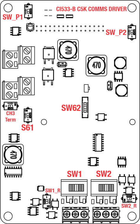
Channel 1. CH1 can be configured for the following protocol options using Switch SW1
• COMPAC standard current loop comms
• COMPAC Comms over RS485
• Wayne DART protocol over RS485
If Compac Comms over RS485 for long distances is required (ie greater than 100 metres), set CH1 to RS485 and configure CH1 for Compac in the COMFILL or PT1 settings. Refer to Local setup / Pumps / Comms
For Wayne DART protocol, configure CH1 for RS485 and configure CH1 in Local setup / Pumps / Comms for Wayne DART protocol
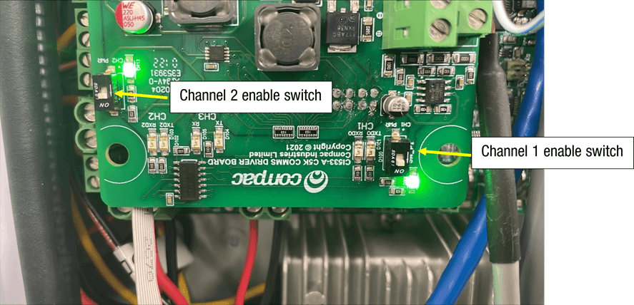
There is an ENABLE switch SW_P1 to turn CH1 ON. A Green LED indicates that the CH1 is ON
When communicating with a Pump or Dispenser, the Tx and Rx red LEDS will flash
SW_P1
This switch is normally left in the ON position
Channel 2 CH2 can be configured for the following protocol options using Switch SW2
• COMPAC protocol over RS485
• GILBARCO protocol
• Wayne DART protocol over RS485
If Compac Comms over RS485 for long distances is required (ie greater than 100 metres, set CH2 to RS485 and configure CH2 for Compac in the COMFILL or PT1 settings. Refer to Local setup / Pumps / Comms
For Wayne DART protocol, configure CH2 for RS485 and configure CH2 in Local setup / Pumps / Comms for Wayne DART protocol
There is an ENABLE switch SW_P2 to turn CH2 ON. A Green LED indicates that the CH2 is ON
When communicating with a Pump or Dispenser, the Tx and Rx red LEDS will flash
SW_P2
This switch is normally left in the ON position
Channel 3 CH3 can be configured for either RS232 or RS485 using Switch S61
CH3 is exclusively used for Tank Gauging Controllers eg Veeder-Root or Calibri
Only RS232 is currently supported on CH3 so the Tank Controller should also be setup for RS232
CI533 Comms board Dipswitch settings
These are the Dip-switch settings for Compac, Gilbarco, Wayne DART and RS485 Comms
SW1
CH1 Channel 1
1 = Compac ( standard Current Loop) comms
2 = RS485
SW2
CH2 Channel 2
1 = Gilbarco
2 = RS485
S61
– CH3 Channel 3 selector switch
ON = RS232
OFF = RS485
SW62
This switch is used for current loop systems on channel 1 (e.g. Gilbarco, Wayne). Adjust the switch according to the current (mA) of the site protocol as required. There are three current options.
Wayne = 45
Gilbarco AUS = 30
Gilbarco USA = 20
CH3 Term, SW1_R and SW2_R
These switches are used for an end of line termination resistor for RS485 applications.
They are not currently supported and should be left in the OFF position
3-1 COMPAC and PEC COMMS
version V1.0 09-08-2021
Connections
The following are the connections and switch settings for Compac/PEC comms on the CI533A.
Note that Channel 2 is free to be used as Gilbarco or Dart
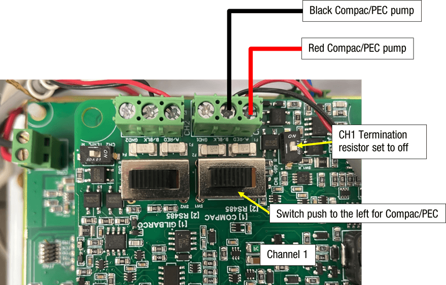
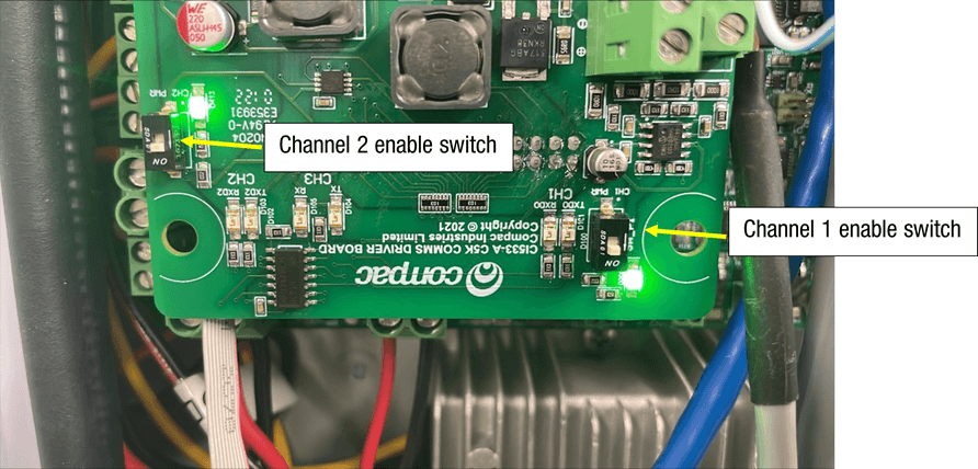
Also, you need to make sure that the Channel that you are using is switched on. When the channel is on, the led indercater will be on.
Configuration / Setup
To set up pumps talking Gilbarco right click on the Site and the click on edit site.
Then click on the pumps tab
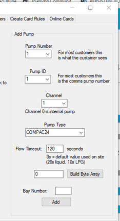
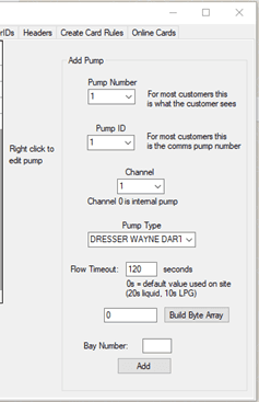
Setup the pump as follows
Pump number: The number of the pump that you will select when prompted
Pump ID: This is the ID set in the pump (normally set the same as the pump number)
Channel: Compac/PEC is always on Channel 1
Pump Type: Set the Pump type “Compac12 ”,“Compac24”, “PEC12” and “PEC12_6digit” Depending on what the Dispenser is set to
Flow timeout: This is the time in seconds after the C5000 says “Ready for delivery” before the c5000 times out and cannels the
authorisation
Then, click the “Add” button
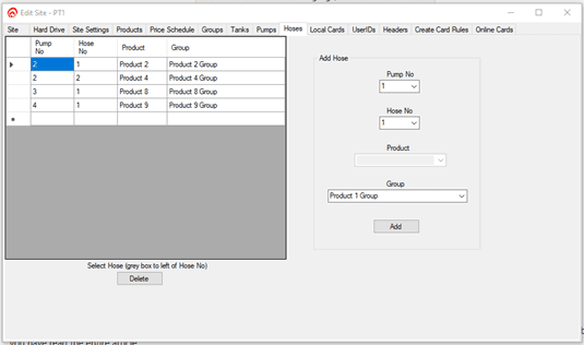
Setup the Hoses
Assign the grades and the hoses on the pump
After the pump is setup in the admin tool, you have to flag the site to update the pump
Setup.
To do this right click on the site and click “Flag status”. Then click “Update Pumps”
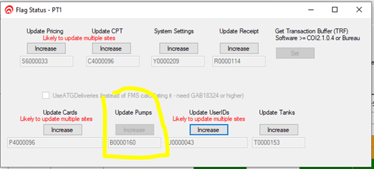
You then can check the events to see if the pumps have been updated
Extra Compac/PEC settings
There are some pumps that need specific settings.
Below is the symptom and the pump type to use.
If you are changing a setting, you MUST reset the C5000 after making the change
Symptom | Setting to use |
|---|---|
The Dispenser seems to keep trying to price change or the price is displayed as $4.123 and it should be $1.234 | If PEC12 change to Compac12 and if Compac12 change to PEC12 |
Compac dispenser. When you enter the auth $10 the pump is stopping at 10 litres because some Compac dispensers only do litres preset | Add the setting below this makes the C5000 work out the litres equivalent and sends it to the pump |
|
3-2 GILBARCO COMMS
version V1.0 9/08/2021
Connections
The following is the connections and switch setting for Gilbarco on the CI533A. Note that Channel 1 is free to be used as Compac or Dart
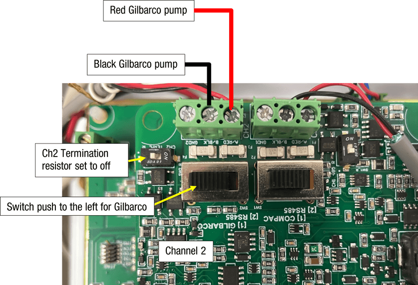
Also need to make sure that the Channel that you are using is switched on. When the channel is on the led indicator will be on.
Configuration / Setup
To set up pumps talking Gilbarco right click on the Site and the click on edit site.
Then click on the pumps tab
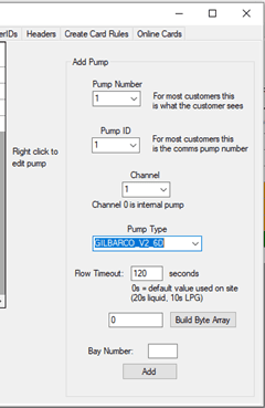
Setup the pump
Pump number: The number of the pump that you will select when prompted
Pump ID: This is the ID set in the pump (normally set the same as the pump number)
Channel: Gilbarco is always on Channel 2
Pump Type: Set the Pump type “GILBARCO_V2_6D” or “GILBARCO_V2_5D” Depending on what the Dispenser is set to
Flow timeout: This is the time in seconds after the C5000 says “Ready for delivery” before the c5000 times out and cannels the authorisation
Then click the “Add” button
Setup the Hoses
Assign the grades the hoses on the pump
After the pump is setup in the admin tool yoy have to flag the site it update the pump
Setup.to do this right click on the site and click “Flag status”. Then click “Update Pumps”
You then can check the events to see if the pumps have been updated
Extra Gilbarco Settings
The C5000 is setup to automatically set the correct Gilbarco protocol. But sometimes the dispenser is a little different. In these cases, we have special Gilbarco protocol versions.
GILBARCO_V2_5D_Preset2D
GILBARCO_V2_5D_Preset4D
GILBARCO_V2_6D_Preset2D
GILBARCO_V2_6D_Preset4D
GILBARCO_V1_5D_Preset2D
GILBARCO_V1_5D_Preset4D
GILBARCO_V1_6D_Preset2D
GILBARCO_V1_6D_Preset4D
Compac Pumps Running Gilbarco need to be set to “GILBARCO_V1_5D_Preset2D” or “GILBARCO_V1_6D_Preset2D”
3-3 DART COMMS
version V1.0 09-08-2021
The following is the connections and switch setting for Dart on the CI533A Ch1 and Ch2
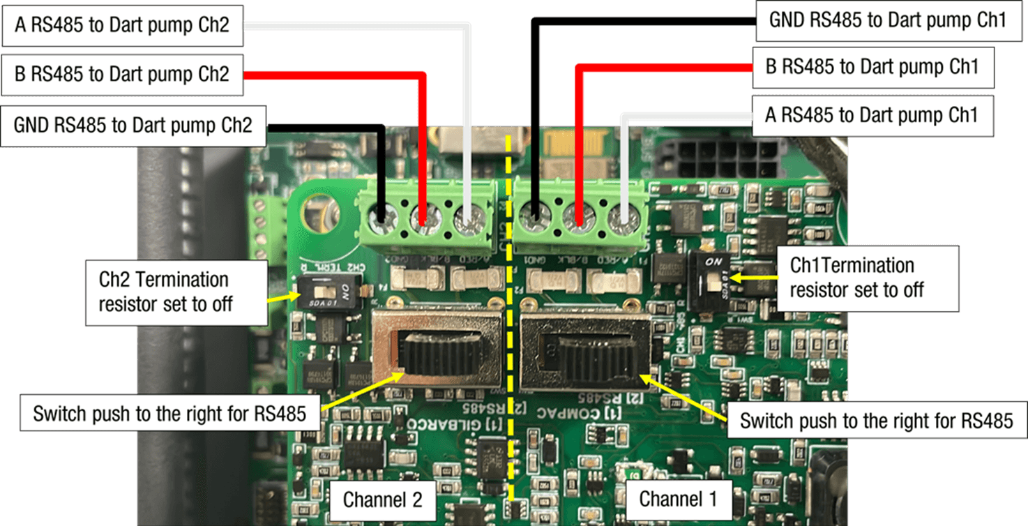
Also need to make sure that the Channel that you are using is switched on. When the channel is on the led indicator will be on.

Configuration / Setup
To set up pumps talking Dart right click on the Site and the click on edit site.
Then click on the pumps tab
Setup the pump
Pump number: The number of the pump that you will select when prompted
Pump ID: This is the ID set in the pump (normally set the same as the pump number)
Channel: The Channel that the pumps are connected to on the CI533 see above
Pump Type: set the Pump type “DRESSER WAYNE DART”
Flow timeout: This is the time in seconds after the C5000 says “Ready for delivery” before the c5000 times out and cannels the authorisation
Then click the “Add” button
Setup the Hoses
Assign the grades to the hoses on the pump
After the pump is setup in the admin tool yoy have to flag the site it update the pump
Setup.to do this right click on the site and click “Flag status”. Then click “Update Pumps”
You then can check the events to see if the pumps have been updated
4 K-Factor Switch settings
A summary of the K-Factor settings can be seen below. Information on these settings and how to change them can be found on the following pages
Setting | Price Display | Litres Display |
|---|---|---|
Dispenser settings | c-A or c-B | ******* |
Meter ID | id-A or id-b | ****** |
Temperature calibration | E-A or E-b | **.* |
Density calibration | d15-a or d15-b | ***.* |
Maximum flow | 9A**** or 9b **** | |
K-Factor | FA or Fb | ***.*** |
Configuration code | c | ******* |
Comms | cc | *** |
Solenoid delay | SdA *** or Sdb *** | |
Preset cutoff | PcA*.** or Pcb*.** | |
Preset rounding | PrLA*.** or PrLb*.** PrHA*.** or PrHb*.** | |
Flow time out | n-A *** or n-b *** |
Dispenser Settings
Changing the C-A and C-b Dispenser settings
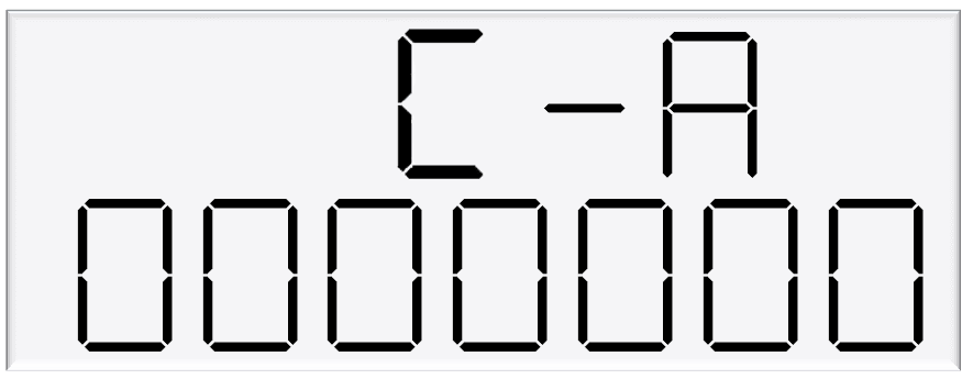
C-A and C-A are used to change the dispenser settings including the meter type, variant and minimum delivery.
To get to the C-A and C-B, press the K-Factor switch once while the dispenser is in an idle state.
The menu shown is for side A – if side B is required, continue depressing the K-Factor switch until the same menu for side B is reached and follow the same set up instructions.
Caution: These settings are likely to have been set correctly in the Compac factory. Only change if required. See following pages for information on these settings.
Setting | Digit | Function |
|---|---|---|
C-A or C-B | 1st Digit | Minimum Measured Quantity Coefficient – MUST be 1, 2 or 5 |
2nd digit | Minimum Measured Quantity Exponent – Must be a valid digit- see below | |
3rd digit | Not used | |
4th digit | Air Switch settings | |
0 = Normally open – turn air switch ON for error | ||
1 = Normally closed – turn air switch OFF for error | ||
5th digit | Quantity Settings - V50 Meter only | |
0 = Litres Compensated | ||
1 = Litres Uncompensated | ||
2 = Mass (CNG only) | ||
6th Digit | Variant Settings | |
0 = Non-LPG | ||
4 = AdBlue (Diesel Emissions Fluid or DEF) | ||
5 = LPG | ||
7th Digit | Meter settings | |
1 = 1 Channel Encoder | ||
2 = 2 Channel Encoder | ||
3 = 3 Channel Encoder | ||
4 = V50 or KG100 Meter | ||
5 = GPIO Meter input |
Meter Settings
This setting corresponds to the type of meter plugged in to the dispenser. Options 1-3 are for an encoder meter and depend on the channel setting of this meter. Encoder meters are used for petrol and diesel, while V50 meters (option 4) are used for LPG and AdBlue. Some settings (such as temperature and density calibration) are only available for V50 and therefore will not appear if the meter type is not set to V50.
Variant Settings
This setting should be changed depending on the product – set the variant to 0 for liquid fuels such as petrol or diesel. Set the variant to 4 for diesel emissions fluid (AdBlue). Set the variant to 5 for LPG.
Quantity Settings
This setting is what quantity will be shown on the main display when fuel is being dispensed. This is only valid for V50 meters and is ignored for encoder meters which always display Litres uncompensated.
Air Settings
Air switches can be turned on or off to trigger this error, depending on this setting.
Minimum Measurable Quantity (MMQ)
Minimum measured quantity (MMQ) is the minimum amount of fuel that can be dispensed and measured. The MMQ is calculated with the following equation:
MMQ=M x 10^n
With the value in litres. For example, if the coefficient was set to 2, and the exponent was set to 1:
MMQ=2 x 10^1=20L
So the minimum delivery would be 20 litres.
The exponent can only be certain values;
If the coefficient is 1, the exponent can be 0, 1, 2, 3 (valid values are then 1, 10, 100, 1000)
If the coefficient is 2, the exponent can be 0, 1, 2 (valid values are then 2, 20, 200)
If the coefficient is 5, the exponent can be 0, 1, 2 (valid values are then 5, 50, 500)
If either of the values entered are not valid, or the value is left as 00, the MMQ will be calculated from the maximum flow. The MMQ is the maximum flow x 0.05. For example, if the maximum flow was 40 (the default):
MMQ=40 x 0.05=2L
Note that the MMQ still must be one of the valid values listed above. If the MMQ is calculated from the maximum flow, and is NOT one of the valid values listed above, it will be rounded up to the next valid value. For example, if the maximum flow was 600:
MMQ=600 x 0.05=30L
30L is not a valid value, and therefore the MMQ would be rounded up to 50L.
The MMQ sets the display suppression. When a transaction starts, the quantity dispensed will not show until a percentage of the MMQ has been dispensed. For LPG, display suppression is 4% of the MMQ. For non-LPG operation, display suppression is 2% of the MMQ. For example, if the dispenser is in LPG mode and the MMQ is 2L:
2 x 0.04=0.08
So the quantity dispensed will not show until more than 0.08L has been dispensed.
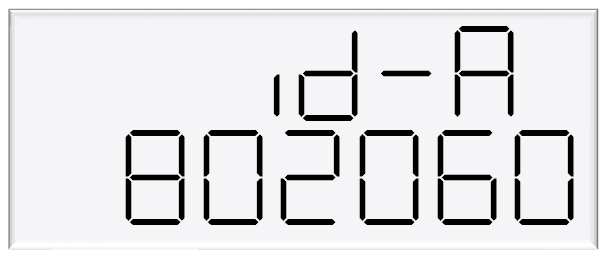
Changing the V50 Meter ID
All V50 Meters have a specific ID which must match the ID recored in the Dispenser settings
This is a 6 digit number which can be found written on the V50 Meter
80206 as in the image below is an example of a Meter ID
If the IDs do not match, the Dispenser will return an error
Meter IDs ae only relevant for V50 operation. That is LPG, DEF or Adblue
This option will not appear if the Meter is not set to V50
See using the Dispenser Menus to edit these settings. Use the procedure for both Side A and Side B
Changing the Temperature Calibration E-A and E-b
The Temperature calibration can be used to adjust the Temperature being retrieved from the meter, if this is not the actual Temperature of the product being dispensed, then the actual temperature of product being dispensed should be entered in this menu. This will be used to adjust new temperatures returned from the meter.
See Using the Dispenser Menus to edit these settings. Use the procedure for both side A and B.

As only V50 meters return temperature readings, this option is only for V50 operation and will not appear if the meter is not set to V50
Changing the Density Calibration dIS-A
The density calibration can be used to adjust the density being retrieved from the meter, if this is not the actual density of the product being dispensed. The actual density of product at 15 °C being dispensed should be entered in this menu. This will be used to adjust new densities returned from the meter.
See Using the Dispenser Menus to edit these settings. Use the procedure for both side A and B.
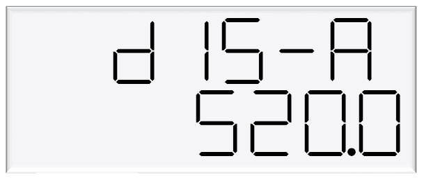
As only V50 meters return density readings, this option is only for V50 operation and will not appear if the meter is not set to V50
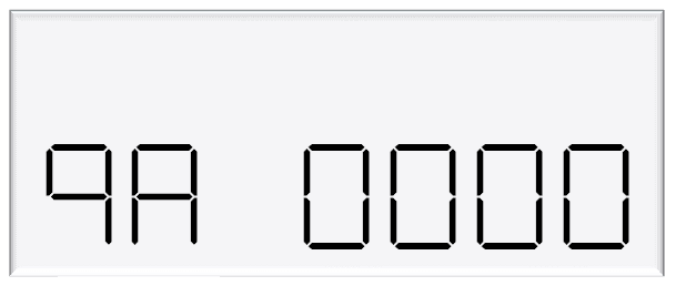
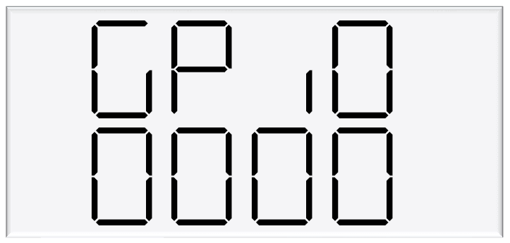
Changing the Maximum Flow rate 9A and 9b
If this setting is left at 0000, the maximum flow rate, or Qmax, is 40 litres/minute by default. When changing the maximum flow, note that the high flow cutoff, low flow cutoff (LPG only), MMQ, and preset rounding are calculated from the maximum flow.
See Using the Dispenser Menus to edit these settings. Use the procedure for both side A and B.
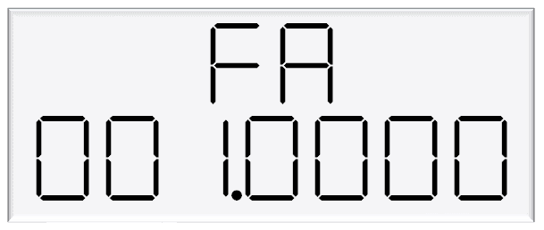
Changing the K factor FA and Fb
The K-Factor is used to calibrate product flow. It is a ratio of litres dispensed per revolution of the meter. The K-Factor may need to be calibrated after periods of time.
To calibrate the pump, dispense fuel into a certified measuring container and compare the display value with the one dispensed.
Example:
The Display shows 10.00 litres but the True volume is actually 20.00 Litres
To calculate the correct K-Factor from the information above; firstly record the existing K-Factor and use this formula to calculate the new K Factor.
New K Factor=Existing K Factor x (Dispensed Amount)/(Displayed Amount)
=Existing K Factor x 20/10
=Existing K Factor x 2
See Using the Dispenser Menus to edit these settings. Use the procedure for both side A and B.
Default K Factor setting
All Compac Meters have a default K Factor setting which is set at tiem of manufacture of the Compac Product that it is installed in.
This default K Factor will be very close to the final k Factor once the equipment is calibrated on site.
Default K Factors for Compac Meters used in compac equipment are as follows
Meter model number | Default K Factor | Product |
|---|---|---|
COM50 | 0.6450 | Petrol/Diesel |
COM125 | 1.1125 | Petrol/Diesel |
COM250 | 2.1600 | Petrol/Diesel |
V40 | 1.000 | Adblue DEF |
V50 | 1.000 | Adblue DEF |
V50 | 1.000 | LPG-if dispensing in Litres |
KG80 and KG100 | 0.2500 | CNG |
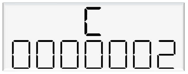
Changing Configuration C
The Dispenser has settings for each side (as previously shown) as well as configuration settings for the entire unit.
Use the following diagram to set the unit up as desired.
Setting | Digit | Indication |
|---|---|---|
C | 1st digit | Hardware Variant |
0 - Dispenser | ||
1 - Hybrid | ||
2nd digit | unused | |
3rd digit | unused | |
4th digit | Sump | |
0-Sump | ||
1-Lo fuel | ||
5th digit | Card totals & Sump | |
0 - Card totals enabled | ||
1 - Card totals disabled | ||
2 - Sump/Lo fuel separate | ||
3 - Card totals disabled & Sump/Lo fuel separate | ||
4 - Push to Start | ||
6th digit | Pump Mode | |
0 - Retail | ||
1 - Commercial | ||
7th digit | Pump settings | |
1 - Single | ||
2 - Dual | ||
4 - Dual 160 | ||
5 - Dual HSB |
Hardware Variant
The hardware variant refers to the type of dispenser and should always be set to 0 – Dispenser for dispenser application.
Card Totals
Card totals record the delivery totals for given cards. This is enabled by default but can be disabled if desired.
Pump Mode
The dispenser can be switched between retail or commercial, depending on the application.
Pump Settings
Each setting is a different configuration with different hardware. See below for descriptions of these configurations.
For all pump settings, the main display shows information on side A. Slave displays will need to be configured to show side B.

Single Pump or Dispenser
In single mode, one outlet is used to dispense one product. The price per litre window for side B is not used.
In this setting, only side A settings will appear in the menus.
Dual Pump or Dispenser
In Dual mode, the dispenser or pump has two outlets which can be used separately, at the same time. Each outlet can be configured separately. Two separate products can be used. Side A supports high flow.
Dual 160 Dispenser
In Dual 160 mode, the dispenser has two outlets, however they must dispense the same product. Either outlet can support high flow and both outlets can be used simultaneously.
Dual 160 mode can only be used in dispenser application, and not for pump application.
Dual HLB Pump or Dispenser
In Dual HLB mode, the dispenser or pump has two outlets which can be used separately, at the same time. Each outlet can be configured separately. Two separate products can be used. Side B supports high flow.
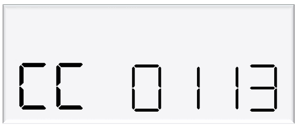
Changing COMMS CC
Use the following table to setup COMMS as required.
Setting | Digit | Indication |
|---|---|---|
CC | 1st digit | Unused |
2nd digit | Mode | |
1 = 5 digit | ||
0 = 6 digit | ||
3rd digit | Channel | |
0 | ||
1 = default channel | ||
2 | ||
4th digit | Pump Protocol | |
0 = Disabled | ||
1 = Compac | ||
2 = PEC | ||
3 = Gilbarco |
Change the Protocol and the mode to match the controller’s settings. Channel 1 is the default channel for dispensers (channel number should always match the with the comms board terminal block used).
E.g. CC = 0113 Gilbarco on Channel 1, 5 Digit mode
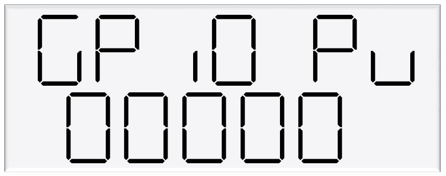
Changing the Display Decimal Points
In some countries, the decimal place needs to be configured because of the currency in that country.
Setting dP A/B allows you to configure the decimal place for each of the values on the LCD display:
Amount (e.g., $)
Quantity (e.g., litres)
Amount/Quantity (e.g., $ / Litre)
The decimal place setting is after the communications setting on the K-Factor button.
Settings are from left to right (1st setting is on the left):

Setting | Digit | Indication |
|---|---|---|
dP A | 1st digit | Decimal Point options |
1 = Match price and amount DP config to pump comms (controller) | ||
2 = Don't match price and amount DP to pump comms. Allow Amount DP to dynamically shift to 0dp | ||
2nd digit | Amount ($ or other currency) Decimal place | |
0 = Default (2dp) | ||
1 = 1dp | ||
2 = 2dp (default) | ||
9 = 0dp | ||
3rd digit | Quantity (litres or other unit of measure) Decimal place | |
0 = Default (2dp) | ||
1 = 1dp | ||
2 = 2dp (default) | ||
9 = 0dp | ||
4th digit | Amount / Quantity ($ per litre or other units) Decimal place | |
0 = Default (2dp) | ||
1 = 1dp | ||
2 = 2dp (default) | ||
9 = 0dp |
Example
If dP A is set to 1921, the display will appear as:
000000→ Amount ($) = 0dp0000.00→ Quantity (Litres) = 2dp000.0→ Amount/Quantity ($/litre) = 1dp
This setup is used in Vanuatu.
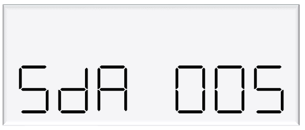
Changing the Solenoid Delay SdA
Pumps have two solenoids for product flow. If the solenoids are unavailable, the pump preset should also be unavailable.
The solenoid delay is the time between when the motor starts, and when the solenoids start at the beginning of a transaction.
The value entered is in seconds.
See Using the Dispenser Menus to edit these settings. Use the procedure for both side A and B.
Changing the Preset cutoff
Preset cutoff is used to deliver an accurate amount of fuel.
When dispensing fuel, two solenoids are used for fuel flow.
When the dispensed amount of product reaches the preset cutoff, one solenoid is turned off to slow delivery rate and dispense an accurate volume of product.
The entered value should be in litres – for example, if 1.50 is entered, and the preset is 10, the primary solenoid will cut off once 8.5 litres have been dispensed.
See Using the Dispenser Menus to edit these settings. Use the procedure for both side A and B.

Changing the Preset Rounding
The dispensed amount of fuel can be rounded to the preset if within the preset rounding parameters.
If the preset rounding is left as zero, the preset rounding will be calculated from the MMQ.
In LPG mode, 2% of the MMQ will be used for preset rounding.
In non-LPG mode, 1% of the MMQ will be used for preset rounding.
For example, if the dispenser is in LPG mode and the MMQ is 2L:
2 x 0.02=0.04
Therefore, if the dispensed value is within 0.04L of the preset, it will be rounded to the preset.
A high and low amount can be entered, which will be used to round the preset.
The measurement is in litres. For example, if .80 was entered for the low amount, and the preset was 40L:
39.20 is within .80 of 40 and would therefore be rounded up to 40.
If 2.00 was entered for the high amount, and the preset was 40L:
42.00 is within 2 of 40 and would therefore be rounded down to 40.
See Using the Dispenser Menus to edit these settings. Use the procedure for both side A and B.
Changing the Preset Rounding
The dispensed amount of fuel can be rounded to the preset if within the preset rounding parameters. If the preset rounding is left as zero, the preset rounding will be calculated from the MMQ. In LPG mode, 2% of the MMQ will be used for preset rounding. In non-LPG mode, 1% of the MMQ will be used for preset rounding. For example, if the dispenser is in LPG mode and the MMQ is 2L:
2 x 0.02=0.04
Therefore, if the dispensed value is within 0.04L of the preset, it will be rounded to the preset.
A high and low amount can be entered, which will be used to round the preset. The measurement is in litres. For example, if .80 was entered for the low amount, and the preset was 40L:
39.20 is within .80 of 40 and would therefore be rounded up to 40.

If 2.00 was entered for the high amount, and the preset was 40L:
42.00 is within 2 of 40 and would therefore be rounded down to 40.
See Using the Dispenser Menus to edit these settings.
Use the procedure for both side A and B.

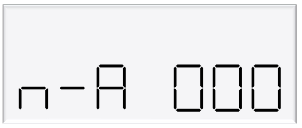
Changing the Flow Time Out
The flow time out is the amount of time it takes for the transaction to time out after flow stops, if the nozzle is not hung up.
The default depends on the dispenser mode.
If the dispenser is in LPG mode, the default time out will be 10 seconds.
In non-LPG mode, the default time out will be 20 seconds.
If a different value is desired, enter this value in the menu below, in seconds.
The maximum flow time out is 120 seconds.
If a value above 120 seconds is entered, the flow time out will stay as 120 seconds.
See Using the Dispenser Menus to edit these settings. Use the procedure for both side A and B.
5 Parameter Switch Settings
The following table summarises the parameter switch settings.
Information on these settings and how to change them can be found on the following pages.
NOTE: The configuration settings must be set before parameter settings can be accessed.
Setting | Price Display | Litres Display |
|---|---|---|
Software Version | P**.**. ** | P**.**. ** |
Pump Number | PnA *** or PnB *** | |
Price | PA**.*** or Pb**.*** | |
Pump Settings | ba **** or bb **** | |
High Preset cut off | HCA** or HCb** | |
High-flow cut off | HFA*** | |
Low-flow cut off | LFA*** | |
b Setting | b**** | |
Slave display | d5 **** | |
Custom display | dc **** | |
Last Sale | . | A***.* or b***.* |
Electronic Totes | LA **** or dA**** | L****.** |
Lb **** or db**** | d****.** |
Using the Dispenser Menus
When changing settings on the dispenser, pressing the Parameter switch in quick succession cycles between the options available.
The location of this switch can be found on page 7.
Each press of the button will cycle between the digits. When going through the menus, each menu will cycle through the digits twice for ease of operation.
When a digit is flashing, hold down the relevant switch to increment this digit.
Release the switch on the desired value.
The system timeout is 10 seconds.
How to view the Software Version
Pressing the parameter switch once will show the software version.
The dispenser will then run through a segment test.
Changing the Pump Number
If the parameter switch is continually depressed, the following menu to change the pump number will appear. Each side must be numbered between 1-99.
NOTE: Entering a pump number 0 will disable the pump.
See Using the Dispenser Menus to edit these settings. Use the procedure for both side A and B.

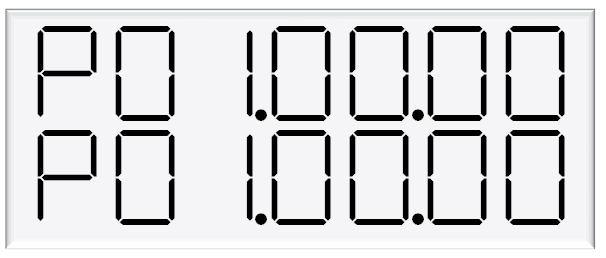
Changing the Price
The price must be set before the dispenser can be used, otherwise an error will be returned.
Set the price in dollars per litre.
See Using the Dispenser Menus to edit these settings. Use the procedure for both side A and B.

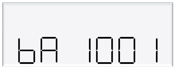
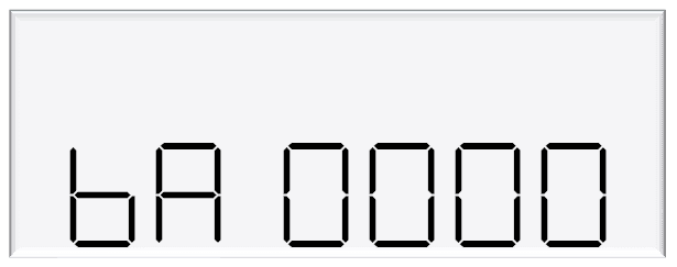
Changing the Pump settings
The pump can have different modes, which can be set using the table diagram below.
See below for information on these modes.
See Using the Dispenser Menus to edit these settings.
Use the procedure for both side A and B. If the dispenser is in multi product mode (see page 17) there are only settings for side A, which will apply to the whole unit.
Setting | Digit | Indication |
|---|---|---|
bA | 1st digit | Pump Settings |
0 = Authorisation Mode | ||
1 = Standalone Mode | ||
2nd digit | Preset Setting | |
0 = Preset in dollars | ||
1 = Preset in litres | ||
2 = Switchable | ||
4 = Forced Preset in Dollars | ||
5 = Forced Preset in Litres | ||
6 = Forced Preset, switchable | ||
3rd digit | Not used | |
4th digit | Dispenser Modes | |
0 = Standard Mode | ||
1 = Purge Mode | ||
8 = Auto-Authorisation |
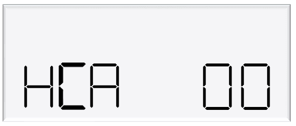
Changing the High Preset Cut
The settings HCA and HCB are used in high flow applications as an extra flow control.
This setting is the number of litres before the preset that the output will switch off.
It is used when extra high flow control is needed.
The PCA and the PCB settings have a maximum setting, up to 9.99 litres, where-as the HCA and HCB can be set to a maximum of 99 litres.
In the MR400S, it is used to control the 2” extra High flow valve but this setting could also be used to control an extra high flow valve in a Volume Register application.
In an MR400S dispenser, HCA is normally set to 20.
Note: To use the HCA (high cut),it is also necessary to short the pins together on plug H/L A (or H/L B) on the k-factor board
Pump settings on Parameter switch explained
Standard Mode
In standard mode, the main display will show:
Top row: Transaction total in dollars
Second row: Compensated litres for LPG, or uncompensated litres for non-LPG, dispensed by default, but can be changed in Dispenser Settings
The unit price window will display the price per litre.
Purge Mode
Test mode can be used for all calibrated runs with the exception of vapour tests.
When in purge mode, the following is displayed on the main display:
Top row: Purge
Second row: Uncompensated litres dispensed
If the meter setting is set to V50 meter, the unit price window will alternate between showing temperature and density at 15 °C.
If the density is outside of the compensation range, then the observed density will be displayed.
This information is obtained from the V50 meter.
If the meter settings are set to encoder meter, the unit price display will show flowrate.
In purge mode, all display suppression is turned off.
Preset Options
A preset in dollars or litres can be set. Before a transaction, type in a desired preset value.
There are three options for setting a preset:
Dollars – the preset will be shown in the top row of the main display
Litres – the preset will be shown in the bottom row of the main display
Switchable – The preset can be switched between dollars and litres by holding ‘#’ for three seconds when not in a transaction.
The above three options can be set up to be either Optional Preset or Forced Preset
Presets can still be entered during a transaction, as long as flow has not started.
Enter a preset by using the keypad.
Pressing # will clear a preset. As soon as flow starts, the preset can not be changed, however, pressing the # key during the transaction will display the preset amount.
Pressing # after a transaction will recall the last preset. This will then be used for the next transaction, if it is displayed when the nozzle is picked up. This is useful for multiple transactions in a row requiring the same preset.
Presets entered must be larger than the MMQ. If the MMQ is large, when entering a preset after lifting the nozzle, the MMQ will automatically show up.
Continue entering the desired preset to override this.
If entering a preset before lifting the nozzle, and a value below the MMQ is entered, an error code will be returned.
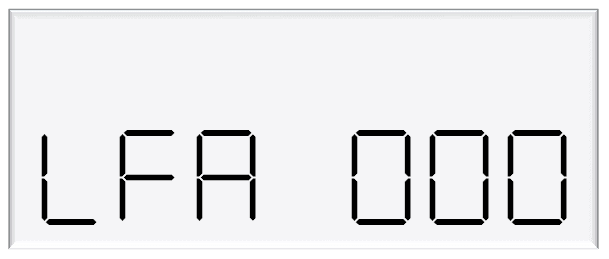
Changing the Low-flow Cutoff
A flow range is needed for each pump to dispense an accurate amount of product.
If too much or too little fuel is dispensed, the meter can not accurately measure the dispensed fuel and therefore should cut off and display an end of sale message.
The low-flow cutoff will end the transaction (without an error code) if flow drops below this value.
In LPG operation, the default value for the low flow cutoff is 0.1x the maximum flow. For example, if the maximum flow was 40L/min (the default):
LF=0.1 x 40=4L/min
If a custom value is desired, enter the value in this menu in litres.
In non-LPG mode, the low-flow cutoff only applies if a custom value is entered.
See Using the Dispenser Menus to edit these settings. Use the procedure for both side A and B.
Changing the High-flow Cutoff
The high-flow cutoff will stop transactions if the flowrate exceeds this value, and will return an error.
For LPG operation the default value for the high flow cutoff is 1.5x the maximum flow. For example, if the maximum flow was 40L/min (the default):
HF=1.5 x 40=60L/min
If a custom value is desired, enter the value in this menu in litres.
In non-LPG mode, the high-flow cutoff only applies if a custom value is entered.
See Using the Dispenser Menus to edit these settings. Use the procedure for both side A and B.

Changing the b setting
The b setting is currently only used for LCD dimming. Set the b configuration code as desired.
Setting | Digit | Indication |
|---|---|---|
b | 1st digit | not used |
2nd digit | LCD Dimming | |
0 = Disabled | ||
1 = Enabled | ||
3rd digit | not used | |
4th digit | not used |
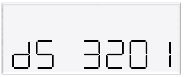
Changing the Slave Display Configuration
Slave displays can be configured as, a clone of the main display, to show side A, or to show side B.
Otherwise, it can be disabled. Slave display configuration is a two-step process.
Change ds setting to assign a side to the slave display
Assign the correct number to the slave display by changing the slave display board dip switches.
Setting | Digit | Indication |
|---|---|---|
dS | 1st digit | Slave display 4 |
0 = Disabled | ||
1 = Clone | ||
2 = Side A | ||
3 = Side B | ||
dS | 2nd digit | Slave display 3 |
0 = Disabled | ||
1 = Clone | ||
2 = Side A | ||
3 = Side B | ||
dS | 3rd digit | Slave display 2 |
0 = Disabled | ||
1 = Clone | ||
2 = Side A | ||
3 = Side B | ||
dS | 4th digit | Slave display 1 |
0 = Disabled | ||
1 = Clone | ||
2 = Side A | ||
3 = Side B |
The first digit from the left correlates to slave display 1, and so on.
In this example,
Slave display 1 = clone
Slave display 2 = disabled
Slave display 3 = side A
Slave display 4 - side B.
Note: Each digit can have 4 different values, each value has a different meaning.
Assigning a number to slave display
Slave Display | Switch 1 | Switch 2 | Switch 3 |
|---|---|---|---|
1 | OFF | OFF | OFF |
2 | OFF | OFF | ON |
3 | OFF | ON | OFF |
4 | OFF | ON | ON |
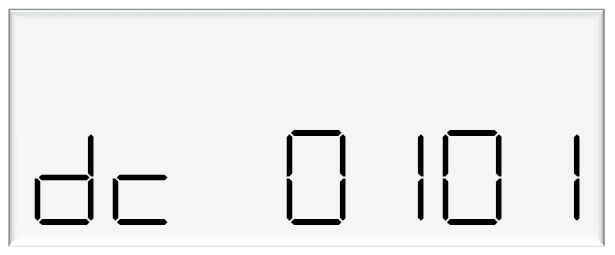
Changing the Custom Display Configuration
The custom display configuration can be used to show additional information on the unit price display.
The additional information that can be shown includes the density, temperature, flowrate, and reset batch.
This can be configured with the dc setting. Each digit corresponds to a custom display option.
Setting a digit to 1, as opposed to 0, enables the custom display. The digits represent the following options:
Digit | Function |
|---|---|
1 | Reset Batch |
2 | Temperature Display |
3 | Density Display |
4 | Flowrate display |
For example: The following code would enable temperature and flowrate to be shown on the custom display
How to view the Last Sale
To view the last sale details, continue pressing the parameter switch until the following display is shown.
This will only show up if the dispenser is in V50 mode.
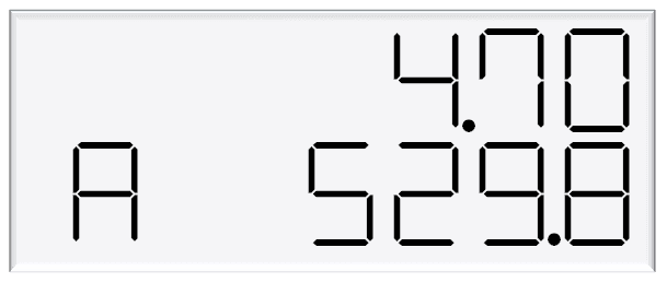
The top row will show uncompensated, unsuppressed quantity dispensed in litres, while the bottom row will show the density reading at 15°C.
The unit price display will show the temperature reading at the end of the sale.
The left most character of the density reading indicates the nozzle side.
There is a reading for side A and B.
Last sale is useful for the calibration of LPG where the dispenser is set to compensated mode, but the uncompensated quantity is required
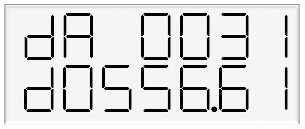
How to view Electronic Totes
The dispenser records electronic totes for price and dollars.
To view the electronic totes, continue pressing the parameter switch until the following display is shown:
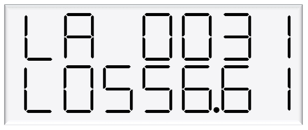
The bottom row is a continuation of the top row.
For example, the above display should be read as 00310556.61.
The side (A or B) will be shown in the unit price display.
Dollars totals are also recorded, which can be viewed by continually pressing the parameter switch.
The electronic totes can also be viewed by pressing the # key five times on the main display, as long as the unit is not in a transaction.
Each tote will be shown for ten seconds before the next tote is displayed.
NOTE: Electronic totes and mechanical totes are disabled in purge mode.
Enabling Amount or Quantity Preset
Enable from CompacOnline Admin tool
Follow these steps:
Step number | Instruction |
|---|---|
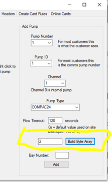
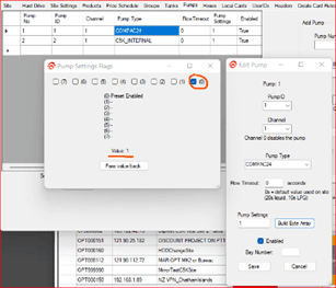
1 | In Pump settings, select Edit pump and click on Build Byte Array |
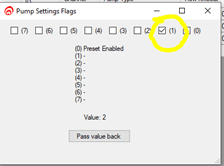
2 | Ensure 0 is selected to enable Preset |
3 | Click on Pass value back and close the Edit page |
4 | Flag the site to update the pump settings |
Changing presets between Amount and Quantity
This can be achieved in two ways:
Using the Pinpad on the COM5
Through Parameter settings on K-Factor board
Using the Pinpad on the COM5 to configure Preset
Step number | Instruction |
|---|---|
1 | Press Cancel button and enter Passcode |
2 | On the Main Menu, Select 3. Pumps |
3 | On the Pumps menu, Select 1. Side A (or select corresponding pump) |
4 | Side A Config 1 – Press # key for next screen |
5 | Side A Config 2 – Select 3. Preset |
6 | Preset Config – Select 2. To cycle between Amount; Quantity or Switch |
Parameter Settings on K-Factor board – navigate to Pump Settings
Change preset setting 0 or 1
Changes to Prompts displayed
When changing between Amount or Quantity, the prompt display will be updated accordingly.
Digit | Function |
|---|---|
1 | Pump settings |
0 = Authorisation Mode | |
1 = Standalone Mode | |
2 | Preset setting |
0 = Preset in dollars | |
1 = Preset in litres | |
2 = Switchable between dollars and litres preset | |
4 = Forced Preset in dollars | |
5 = Forced Preset in litres | |
6 = Forced Preset which is switchable between dollars and litres | |
3 | Unused |
4 | Dispenser Modes |
0 = Standard Mode | |
1 = Purge Mode | |
8 = Auto-authorise |
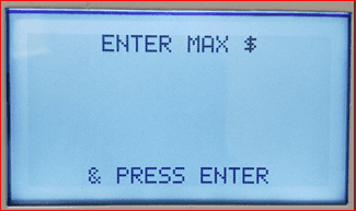
Setting the Preset to Amount:
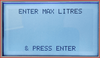
Setting the Preset to Quantity:
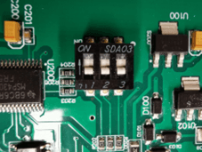
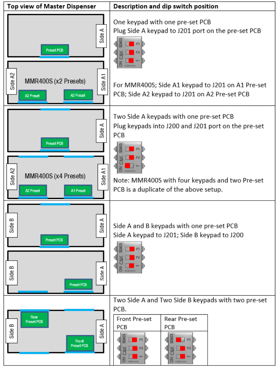
Preset Board DIP Switch settings
Use the diagram below to to determine which layout applies and set the dipswitch accordingly on the Preset board.
GPIO Board applications
GPIO K Factor settings
The GPIO settings in the K factor board is where you set the GPIO specific settings.
This table is common to all GPIO board applicaions
The below table shows details of all the options available for each setting.
Digit | Function |
|---|---|
1st Digit | Duty Cycle Setting |
0 = 50% | |
1 = 10% | |
2 = 20% | |
3 = 30% | |
4 = 40% | |
5 = 50% | |
6 = 60% | |
7 = 70% | |
8 = 80% | |
9 = 90% | |
2nd Digit | Input settings Pulse frequency |
0 = 1Khz | |
1 = 100Hz | |
2 = 200Hz | |
3 = 300Hz | |
4 = 400Hz | |
5 = 500Hz | |
6 = 600Hz | |
7 = 700Hz | |
8 = 800Hz | |
9 = 900Hz | |
A = 1KHz | |
b = 1.1KHz | |
c = 1.2KHz | |
d = 1.3KHz | |
3rd Digit | Output settings |
0 = 0 Off | |
1 = Volume (Litres/KGs) | |
2 = Amount (Dollars) | |
4th Digit | Input settings |
0 = 0 Off | |
1 = 1 Channel Encoder | |
2 = 2 Channel Encoder | |
3 = 3 Channel Encoder | |
4 = Switch Input |
1 GPIO board set up for Pulse Input from a Flow Meter
Overview
The Pulse input is designed to interface the Compac dispenser to a third party meter.
The Pulse input can be up to 35 VDC.
There are 2 settings that need to be set to enable the C5000 for third party meter input.
The first is in the CA/CB setting. CA/CB needs to be set to CA XXXXXX5.
The Pulse input can be configured for the following meter types:
Type 1 - Single channel
Type 2 - Two channel quadrature
Type 3 - Three channel
CA/CB Setting for third party input
To tell the C5000 to read meter pulses from the GPIO board, set the last (7th) digit on the right of CA/CB to 5.
This digit disables the meter input on the K Factor board and tells the C5000 to read pulses from the GPIO board
Setting | Digit | Function |
|---|---|---|
C-A or C-B | 1st Digit | Minimum Measured Quantity Coefficient – MUST be 1, 2 or 5 |
2nd digit | Minimum Measured Quantity Exponent – Must be a valid digit- see below | |
3rd digit | Not used | |
4th digit | Air Switch settings | |
0 = Normally open – turn air switch ON for error | ||
1 = Normally closed – turn air switch OFF for error | ||
5th digit | Quantity Settings - V50 Meter only | |
0 = Litres Compensated | ||
1 = Litres Uncompensated | ||
2 = Mass (CNG only) | ||
6th Digit | Variant Settings | |
0 = Non-LPG | ||
4 = AdBlue (Diesel Emissions Fluid or DEF) | ||
5 = LPG | ||
7th Digit | Meter settings | |
1 = 1 Channel Encoder | ||
2 = 2 Channel Encoder | ||
3 = 3 Channel Encoder | ||
4 = V50 or KG100 Meter | ||
5 = GPIO Meter input |
Third Party Meter wiring
There are different types of meters with different numbers of channels. The below is the meter type and how to wire them to the GPIO Board.
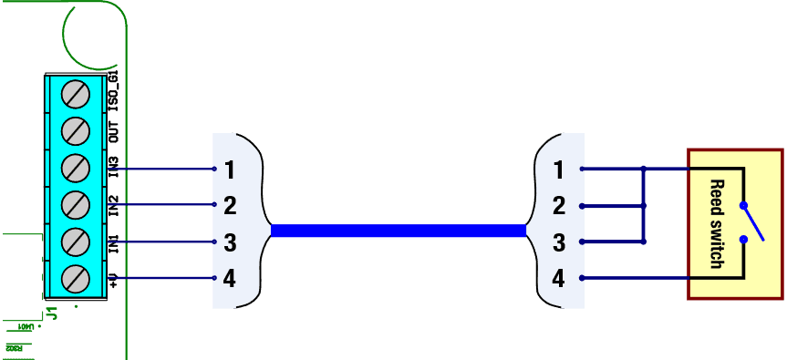
Single Channel Reed Switch Meter
When connecting to a reed switch type meter you connect the GPIO 5-volt to the reed switch and then all 3 inputs to the other terminal on the meter.
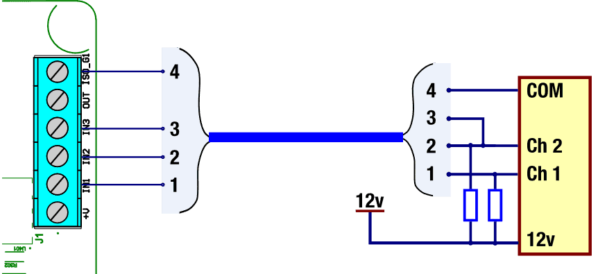
12 Volt Two Channel Meter
The two Channel 12 volt meter is not powered from the GPIO Board.
Instead it is powered by its own power supply. Depending on the meter, pullup resistors may need to be added
5 volt Two Channel Meter
The 2 channel 5 volt meter is powered from the GPIO board.
This means that the meter doesn’t need power from an external source.
Depending on the meter, pullup resistors may need to be added.
For 5 volts the pull up resister should be 820Ω
2 GPIO board set up in Input Switch mode
Overview
The “Nozzle“ input is to act as a control allow or not allow the dispenser to be started.
It is as if there is a switch in series with the real nozzle switch. with means that both nozzles need to be made for the dispenser to start.
Input Switch setting
The setting on the K Factor board to enable the “nozzle Switch“ is GPIO XXX4. That is, the 4th digit = 4
When the switch input is enabled, the dispenser will not start a transaction until the GPIO nozzle input is high and the nozzle input on the k factor board is high (lifted) as well.
Note that if the nozzle is lifted on the K-factor board and the GPIO Nozzle input is low (not shorted) the Diag LED on the K factor board won’t flash. In saying that if you want to troubleshoot the nozzle without the GPIO nozzle input you can disable the switch input by setting the GPIO setting to GPIO XXX0.
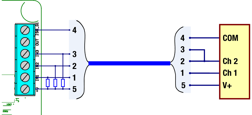
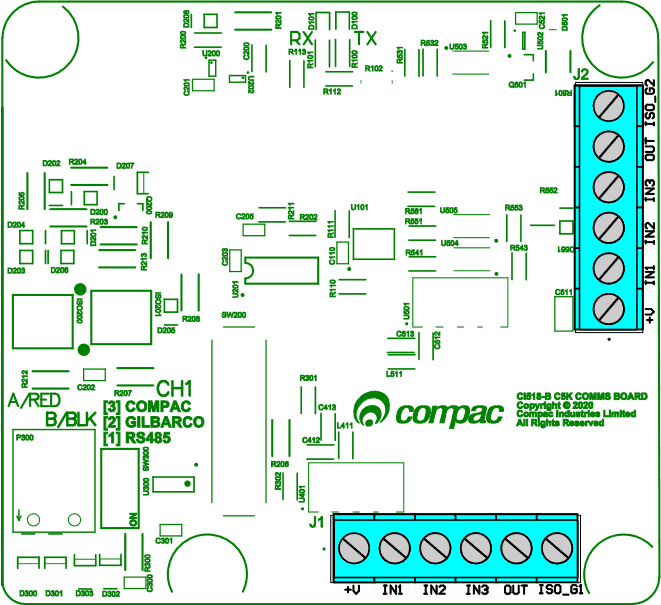
Input Switch wiring
The GPIO nozzle input is wired in to the GPIO board in the flameproof box. The below figure shows the GPIO board and the location of the connectors
Side A connector is labelled J1
Side B connector is labelled J2
There are different ways to connect the GPIO Nozzle input to an external device and the specific way will depend on the application
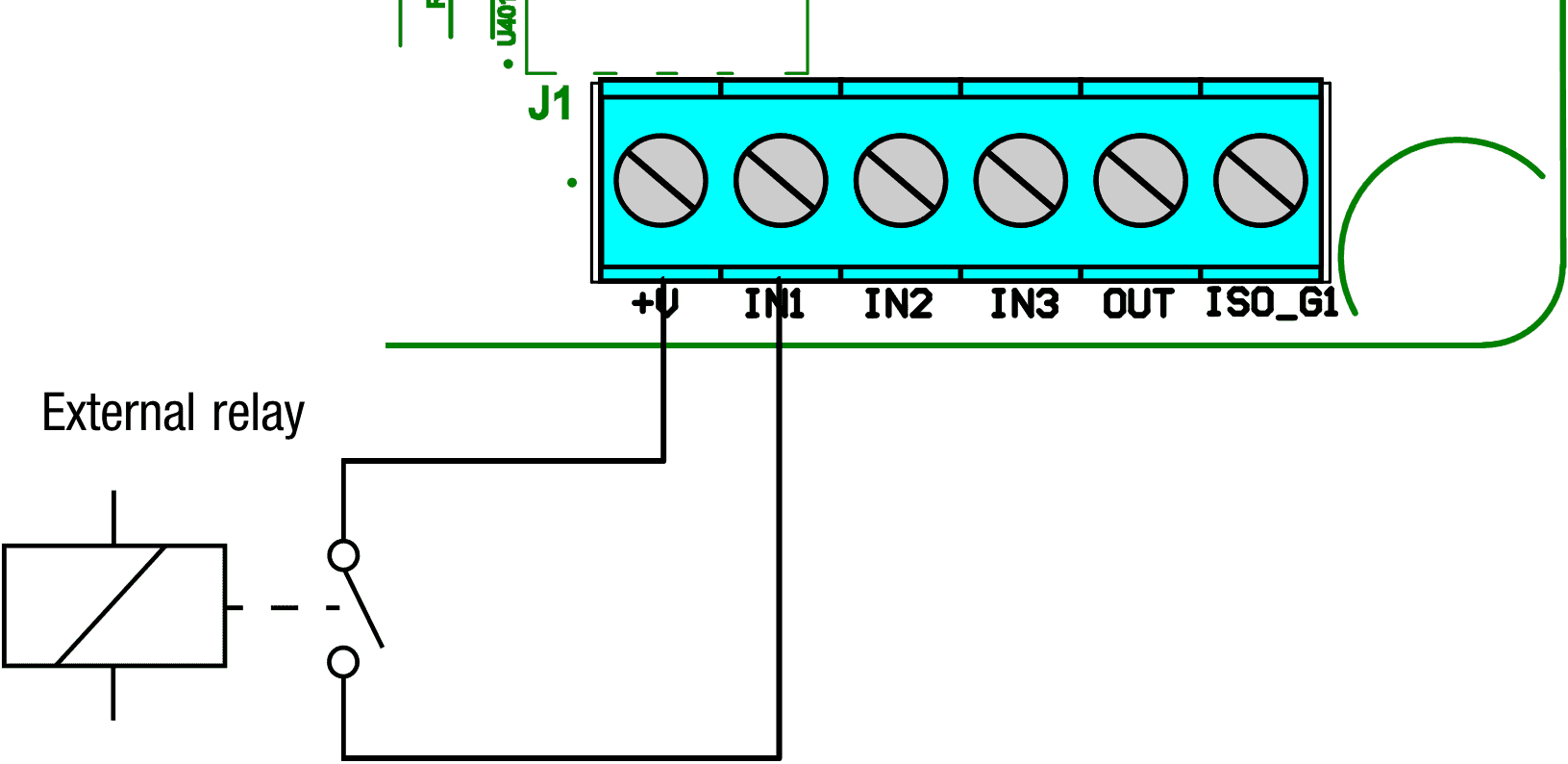
Relay Switch wiring
In this application an external relay is used to enable the GPIO nozzle input.
5 volts from the +V is fed into the relay and the output of the relay feeds back into the GPIO board via the IN1 terminal as shown below.
This means that when the relay is energized the GPIO is pulled high enabling the nozzle.
Use a relay means you can use any voltage AC or DC you just have to source the correct relay for your application
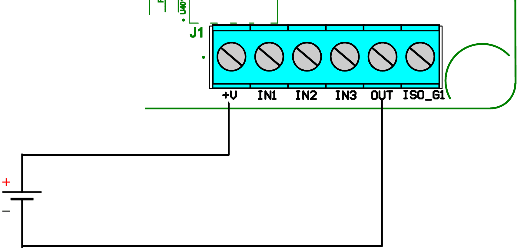
External DC Voltage
In this application, an external DC voltage is applied to enable the GPIO nozzle input.
This DC voltage can be between 3 to 50 volts DC.
The ISO_G1 is connected to the Ground connection of the DC voltage source and the Positive side is connected to IN1.
Note that in the figure below the DC voltage sauce can be from a control system i.e. PLC
3 GPIO board set up in Pulse Output mode
Overview
The Pulse output is designed to interface the Compac dispenser to a 3 party Controller/POS without the need to talk a communication protocol.
The Pulse output has the following parameters that can be changed
• Frequency
• Duty Cycle
• Output pulses for volume or amount
• The Value of a pulse
Output
The output setting enables the GPIO board to output pulses. It also sets whether the output pulses are representing volume(litre/Kg’s) or amount(dollars). Majority of applications will set the pulses to represent volume
Note you cannot have meter input enabled at the same time.
Frequency
The Frequency output setting sets the maximum speed of the output pulses.
The Default setting of 0 sets the frequency to 1KHz.
This setting combined with the Value per pulse setting sets the maximum flow rate of the dispenser.
For example
Frequency set to 1KHz (1000 pulses/sec)
Pulses per value are set to 00001 (10ml/pulse)
That means the maximum flow rate the dispenser can do before the output pulses lag behind is
maximum flow=maxium frequency × pulses per value
maximum flow=1000Hz × 10ml
maximum flow=10000 ml per second
maximum flow=600 l per minute
The default setting of 1KHz should be sufficient for most applications.
In applications where the maximum flow rate is lower and the 3rd party controller is only able to read pulses at a lower frequency then a lower frequency output can be selected.
Note that if the flow rate exceeds the maximum pulse output the next transaction will not be allowed until the pulses have completed being outputted.
Duty Cycle
The duty cycle setting gives the ability to set the percentage of the pulse high and low.
The default setting is 50%. The pulse length is determined by the following formula.
For example
If the Duty cycle is set to 50% and the Frequency is set to 1KHz (1000 pulses/sec)
Duty Cycle=Pulse Width (sec)×Frequency (Hz)×100
50= Pulse Width (sec) ×1000×100
50/100=Pulse Width (sec) ×1000
0.5/1000=Pulse Width (sec)
500 microseconds=Pulse Width (sec)
The Default setting of 50% should be sufficient for most applications.
Pulse value
The pulse value setting sets what a pulse is worth.
When the output is set to volume the lowest volume a pulse can be set to is 00001 which is 0.1 ml.
If the output is set to amount the lowest amount a pulse can be set to is 00001 which is 0.0001 dollars.
The most common setting for most applications would be 00100 or a factor of 10.
Any other setting would cause an error with rounding.
Commissioning
Electrical
This procedure outlines how to perform an electrical operational test, making sure that the dispenser is functioning correctly. Check for any damage that may have occurred in transit. Check all terminals, plugs, and chips to make sure that they are securely in place.
NOTE: Damage to electronics occurs most commonly from vibration and jarring.
Before beginning this test, check that fuel has not been applied to the dispenser. The factory set-up information should be programmed into the dispenser, but all K-factor and Parameter switch settings should be checked and confirmed before commissioning tests are carried out.
Check that pump number is set
Check the pump price is set
To perform an electrical operational test:
Make sure that the inlet shut-off valves are closed (these are the valves in the inlet lines at the base of the dispenser, but they are not part of the dispenser).
Turn on the power supply to the dispenser.
With the dispenser in a ready state, check that the C5000 processor board Power LED is turned on.
NOTE: If the dispenser is receiving information, RD LED on the K-Factor board will be on. If the dispenser responds to polls for its respective pump number/s, TD LED will also be on.
Lift the nozzle. The display will show 888888 and the solenoids will energise, starting the pump motor. Check that T1-3 (side A) or T4-6 (side B) turn on, indicating a signal is being sent to the triacs to open the solenoid valves.
The diagnostic LED (K-factor board) flashes quickly when the start button is pushed, or the nozzle removed from the holster to initiate a fill. When the button is released or nozzle returned to the holster it will return to the normal state and flash slowly.
Verify solenoid operation by listening for a click, or by using a screwdriver tip or some other metallic tool to check for a magnetic field present on the solenoid coils.
Mechanical
The following mechanical commissioning instructions are for liquid fuel pumps and dispensers. If LPG, CNG, or AdBlue is being dispensed, refer to the specific manuals for these.
Make sure that the electrical commissioning tests have been carried out and the solenoid operation has been verified before carrying out the following tests.
Ensure the power supply to the dispenser is turned on, and lift the nozzle. Check all the dispenser fittings, solenoids and pipework for leaks.
Check all bungs have been removed.
Perform test transactions to ensure flow rate is within acceptable ranges and the dispenser is correctly measuring fuel.
If a preset is required, perform test transactions with presets and ensure they are working correctly.
Calibrate the unit with the K-Factor
LED Diagnostics
LEDs on the circuit boards can be used to diagnose faults in the unit.
View the LEDs and their corresponding tables to see the state of the board.
Note These instructions apply to the CI501 Comms interface board which is fitted to standard Pumps and Dispensers
There is also a CI533 Comms board which is used in the PT1 Payment Terminal, Comfill and Fillmaster
Comms board CI501 LEDs | Operation/Possible Cause |
|---|---|
Tx and Rx | Er41, Er 41 or Error 41 means that there is a communication problem between the Pump and the Controller. You can get more detail on what is causing the problem by looking at the two diagnostic LEDs on Comms channel 1 (CH1). |
Compac comms | Rx = Poll from the Controller Tx = Pump Response. |
Compac comms faults | 1. Neither Tx nor Rx are flashing:The Controller is either not working or there is no comms connection between and the Controller and the Pumps. |
Gilbarco comms | Rx = Poll from the Controller |
Gilbarco comms faults | 1. Rx stuck hard on - Tx off and not flashing: |
C5K Processor Board
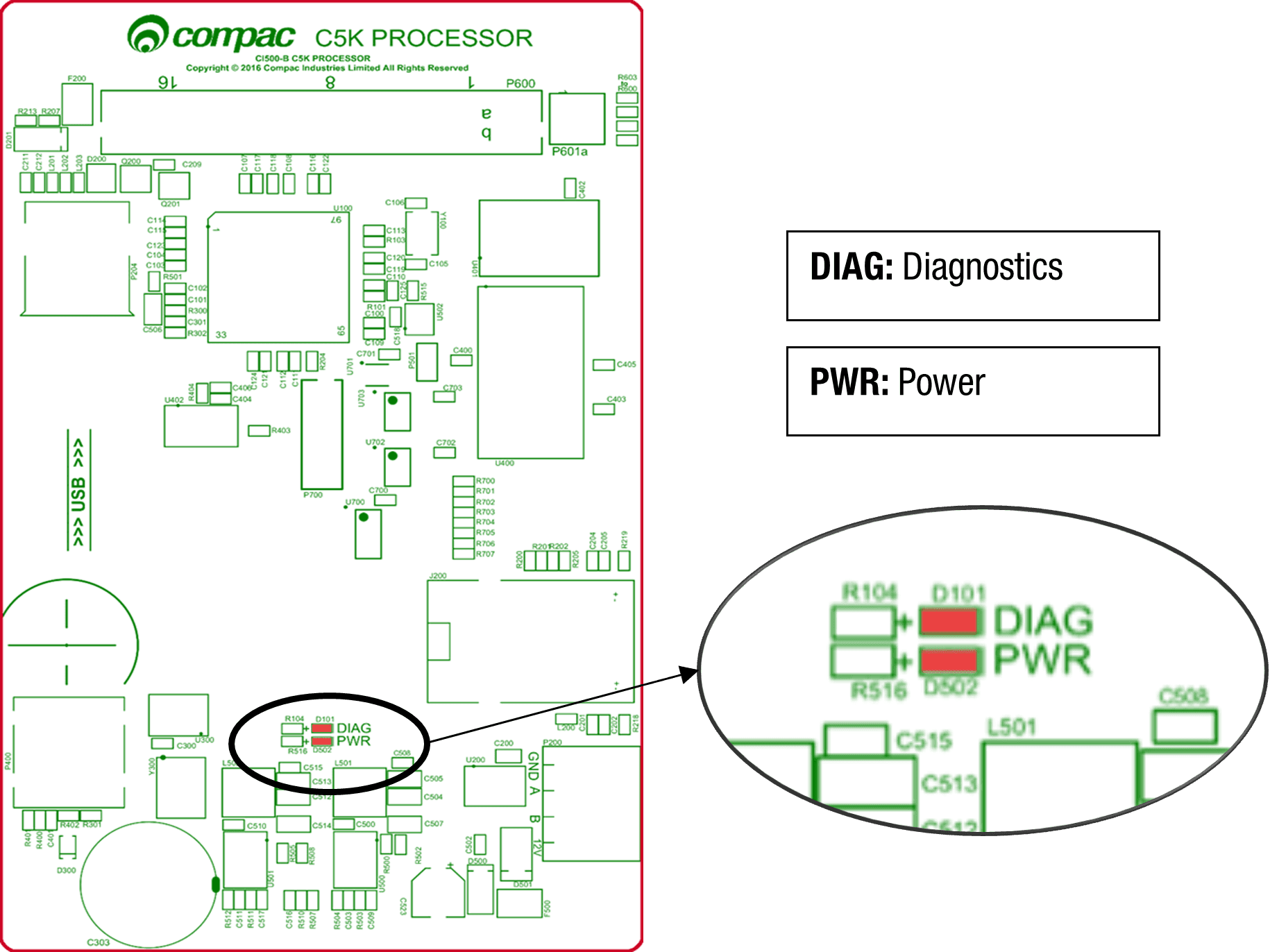
Processor board LEDs | Operation/Possible Cause |
|---|---|
Power | This should be on when there is power to the unit. |
Diagnostics | This LED shows whether the firmware is running for the board. If it is off, the firmware is not running, and if it is on, the firmware is running. |
K Factor board
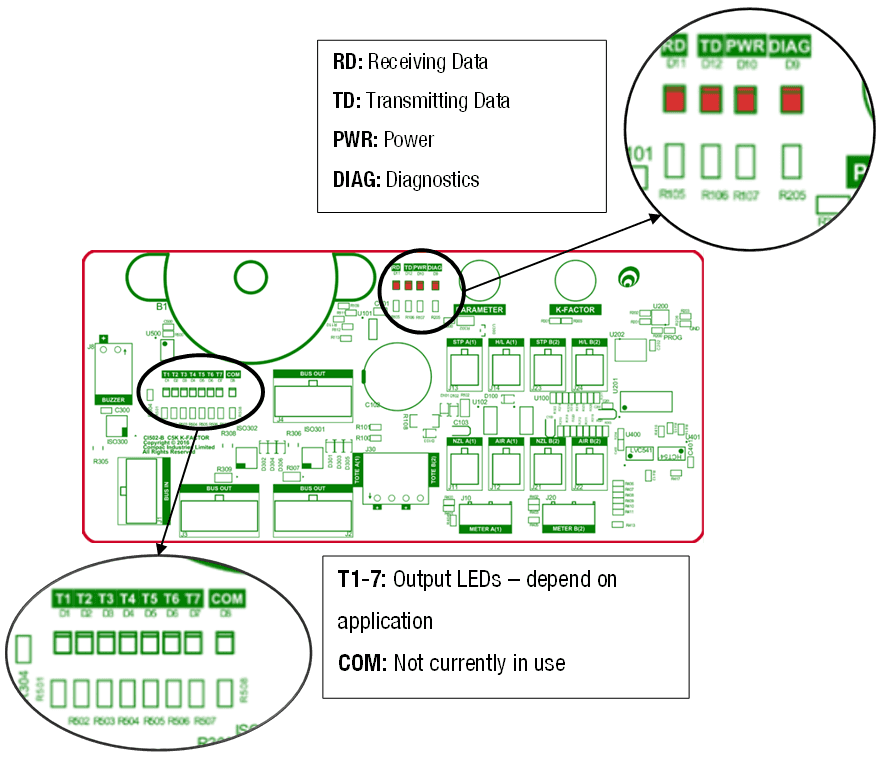
K Factor board LEDs | Operation/Possible Cause |
|---|---|
Power | This should be on when there is power to the unit. |
Diagnostics | In normal operation, this should flash slowly, then flash quickly when the nozzle switch is lifted. |
Triac Output LEDs (T1-7) | These LEDs correspond to side A and B motors and solenoids. |
Receiving data/ Transmitting data | In normal operation, these should be on when the Diagnostics light is on, and off when the diagnostics light is off. |
K Factor Board Output LEDs
The following table describes what each output LED represents for each mode. The output LED will light up when the corresponding outlet is engaged. Outputs for both side A and B are shown.
Mode | T1 | T2 | T3 | T4 | T5 | T6 | T7 |
|---|---|---|---|---|---|---|---|
Single | Motor A | Primary Solenoid A | Secondary Solenoid A | High flow A | Not used | Not used | High FLow A |
Dual | Motor A | Primary Solenoid A | Secondary Solenoid A | Motor B | Primary Solenoid B | Secondary Solenoid B | High FLow A |
Dual 160 | Motor A | Primary Solenoid A | Secondary Solenoid A | High flow B | Primary Solenoid B | Secondary Solenoid B | High FLow A |
Dual HLB | Motor A | Primary Solenoid A | Secondary Solenoid A | Motor B | Primary Solenoid B | Secondary Solenoid B | High FLow B |
Troubleshooting Guide
Electrical problems
Symptom | Possible Cause |
|---|---|
No Power | Check mains power to Dispenser or Pump unit |
No comms | Check comms cable connections |
Pump cuts out | Check End of Sale EOS Indicator on the Parameter Switch to determine what ended the fill |
Pump not starting | Check Triac fuse. |
Pump not stopping | Check that the nozzle switches are releasing. The nozzle switches are working if the Diagnostic LED on the K-Factor board flashes faster when switch is on and slower when it is off. |
Solenoid not energising | Check Triac fuse |
Solenoid Not De-energising | If output LEDs on the K-Factor board are on, check nozzle switch is releasing, the nozzle switch is working if the Diagnostic LED flashes faster when switch is on. |
Preset Display Digit flashing | Check if any preset buttons are stuck in |
PIN Pad Not Working | Check that the unit is communicating with the controller using the RD/TD LEDs. |
Mechanical problems
Symptom | Cause |
|---|---|
Pre-Set Overrun | Solenoid blocked and cannot close or has a damaged piston. |
Calibration Problems | Check that configuration is correct for calibration method - i.e., temperature compensation on or off. |
Solenoid Valve Not Opening | Check the output LEDs on the K-Factor board. |
Software Upgrade
Dispenser Software Upgrade/Replacement
You can upgrade the dispenser software via USB Stick.
Make sure the USB stick is formatted as FAT32 and has the new dispenser software loaded on it.
CAUTION: Before working on the dispenser electronics, take basic anti-static precautions by wearing a wristband with an earth strap.
To record set-up data and tote information:
Access the K-Factor board by opening the cover behind the main display.
Record all the set-up data by accessing the Parameter switch and the K-Factor switch. Refer to Parameter Switch Settings and K-Factor Switch Settings to obtain this information.
The following data is required from the Parameter switch :
Dispenser pump price.
Dispenser pump number.
Dispenser Setting
Software Program number, if you are upgrading to a new version.
The following data is required from the K-Factor switch:
The K-Factor. There is a value for side A and side B in dual hose dispensers.
Configuration Code C.
The Density Factor.
Record the tote information by pressing the nozzle switch or start button quickly five times
To install the new C5000 software
Switch off the power supply to the dispenser.
DANGER: Never remove any electrical components without first switching off the power to the dispenser. Failure to turn off the power could result in an electric shock.
Remove the flameproof box lid to gain access to the C5000 Processor board.
Install the USB stick for the software that you want to install. If there is a coms or GPIO card installed on the C5000 processor board, you might have to remove it.
Re-install the lid on the flameproof box
DANGER: Before replacing the lid on the flameproof box, make sure that the O-ring is not damaged, and is seated properly in its groove. If the O-ring is damaged and needs replacing, replace it with an O-ring of the same size and specification (176 N70).
Switch on the power supply to the dispenser.
The Display will display hold. The display will change from hold to calib, this mean that the software has been upgraded.
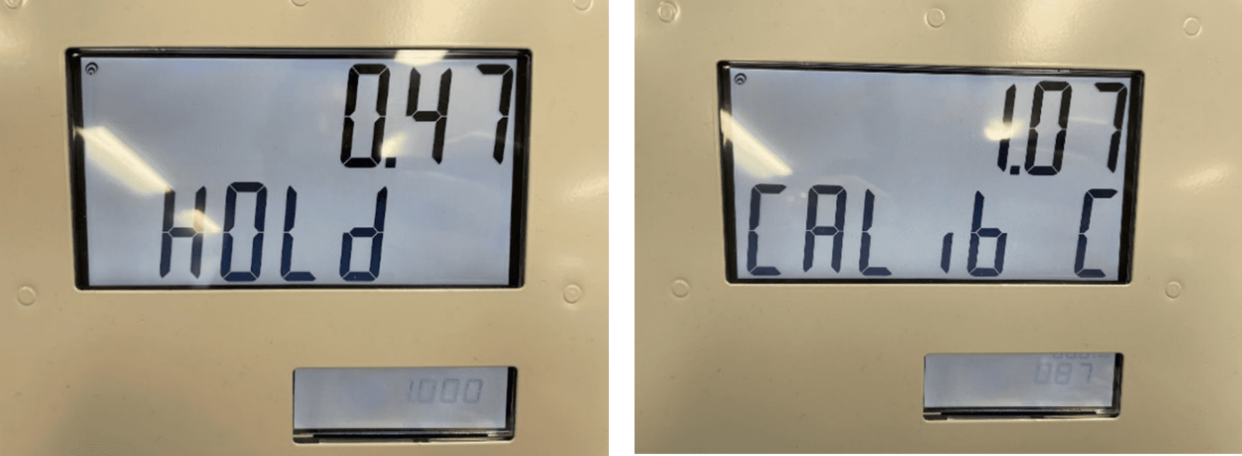
Press the K-Factor board button on the K-Factor board to clear the caib from the display and sync the K-Factor board settings with the C5K processor board.
Check the Dispenser operation.
# Generator Power
The power output from onsite generators can cause power spikes that may damage electrical components within the cabinet.
Although generators are fitted with power regulators, most are not filtered sufficiently for powering sensitive electrical components.
We recommend installing a commercial power conditioner and/or UPS between the generator and the unit.
Start Up:
Before starting a generator, make sure the power to the unit is turned off.
Start the generator, let the generator reach stable operating speed and wait 30 seconds before reconnecting the power to the unit.
For units where the generator starts and stops on demand, install a delay timer or PLC to automatically isolate the unit until the operating speed and consistent power output is achieved.
Isolate the unit before shutting down the generator.
Error Codes
These are all the Error codes available in the C5000. Some are product specific so will not be found in all applications.
Error Code | Fuel specific | Possible causes | Suggested action |
|---|---|---|---|
Er 3 | No | Price not set in the Dispenser | 1. If the Dispenser is connected to a Site Controller, the price on the Dispenser should be set to 0.00 and the pricing should be sent from the Controller |
Er 8 | No | Excessive reverse flow | Check that product is not flowing back into the tank once the delivery has finished. This can occur if the non-return valves on site are leaking |
Er 9 | No | The Flow Meter is in an illegal state | Re-power the Dispenser |
Err91 | No | Meter sequence error | If 3rd party Meter, check the wiring |
Er 10 | No | Memory Error. Configuration data lost or corrupted | Re-configure Dispenser. If problem persists, replace Memory or Processor Board |
Er 12 | No | Display error | Replace Display |
Err 13 | No | Slave board has restarted | Power or Hardware failure |
Err 14 | No | K Factor board offline | Check the Bus Connections and C5K Power Supply |
Err 15 | No | K Factor board has restarted | Power or Hardware failure |
Err 16 | No | K Factor board is not talking to the LCD Display | Check wiring |
Err 31 | No | Transaction has ended but fuel is still flowing | The Solenoid is leaking. Repair or replace solenoid |
Er 41 | No | Pump not communicating with Controller | 1. If only one pump on the site is not communicating with the Controller, then the fault is likely to be in the pump. |
Er 50 | NO | Meter not communicating with Dispenser electronics | a. Check Meter connections |
Er 52 | No | Meter error | If the problem persists after repowering the unit, replace the meter. |
Er 53 | LPG / Adblue / DEF / CNG | Meter stopped ibrating | Repower the unit. This error might display when the dispenser is powered up. In this case it is normal. If the problem persists, replace the meter |
Er 54 | No | Temperature sensor failure | Repower the unit. If the problem persists, replace the meter |
Er 55 | CNG | Meter not ready. | Wait for meter to calibrate itself. The KG100 meter is in startup mode. If the problem persists, repower the unit. |
Er 61 | LPG / Adblue / DEF / CNG | Error 61 happens because the Meter was not able to zero This can be due to a leak in the line or crystals accumulated in the Meter. | |
Er 62 | LPG / Adblue / DEF / CNG | Meter could not reset the batch (Could not zero the transaction values when nozzle was lifted to start a new transaction) | Try restarting the Meter. If the problem persists, Replace the meter. |
Er 71 | LPG / Adblue / DEF | V50 meter is set but variant is not selected | Configure Device to either AdBlue / DEF or LPG |
Abd | No | Display offline / Display Fault | Check the connections to all displays. |
CNG 157 | CNG | The Dispenser expected no flow. Potential Solenoid Valve leak | Repair / rekit Solenoid |
CNG 158 | CNG | Tank volume predictor uncertainty | Check for leaks in the Dispenser hose or fittings |
CNG 159 | CNG | Temperature Probe out of range | Re-calibrate Temperature Probe |
CNG 160 | CNG | Pressure Probe alignment error. There is more than 10bar difference between the two probes | Re-calibrate Pressure Probes (Dispensers with two Pressure Probes per hose) |
CNG 161 | CNG | Temperature Compensation calculation is uncertain | No suggested action |
CNG 162 | CNG | Generic CNG error with a number of potential causes | No suggested action |
CNG 164 | CNG | Pressure Probe error | Check / replace / re-calibrate Pressure Probe. |
CNG 200 | CNG | The Dispenser is detecting unauthorised flow | Gas is flowing without the Start switch having been pressed to start a fill |
hoLd | No | There are two types of HOLD error. There is a “Soft” HOLD err or that resets after the unit is re-powered and a “Hard” HOLD error that does not reset after the unit is re-powered. Display may also show Error 14 on display | Re-power the unit. Does the HOLD error reset? |
Calib c | No | K-Factor data integrity failure, or the processor board has been replaced | To reset, break the K factor switch seal and momentarily press |
Calib p | No | The K-Factor board has been swapped/replaced | To reset, break the K factor switch seal and momentarily press |
Calib | No | The unit needs calibration, usually due to a hardware change | Check the K-Factor, temperature and density calibration |
Calib f | No | K-Factor is not set or is 00.0000 | Calibrate the unit and set the K factor |
Air | No | 1. Air is in the system. 2. Density out of range 3. Coil amplitude too low while meter is operating, displayed until next sale is started | Make sure pump is running. Check tank and pipework for leaks. Purge system. Increase the Solenoid delay on the K-Factor switch |
Orun | No | Preset amount Overrun – flow above preset | Check that solenoid is closing. Increase the preset cutoff |
5ump | No | Sump error – liquid detected in the sump | Empty the sump. Check the dispenser for leaks. Check for water etc getting into the sump. |
Ga5 | LPG | For LPG, the density being returned from the meter is too low | Calibrate meter density using the K-Factor switch |
ABDL | No | Display LCD error | There is a problem with the K Factor Board talking to the LCD. Check cables, plugs etc. If problem persists, replace K Factor board / LCD Display |
Er FLO | No | Excess Flow | Maximum flow rate exceeded, Increase Maximum flow rate setting or restrict flow |
ErPrSt | No | The preset entered is below the MMQ | Enter a preset above (or equal to) the MMQ |
Er dEn | LPG | Density or Temperature out of Range | Calibrate meter density using the K-Factor switch Calibrate meter temperature using the K-Factor switch |
END OF SALE Indicators
The purpose of the END OF SALE Indicator to give the reason why the last fill ended.
This is useful if it is not apparent why the last fill stopped
The EOS number will appear on the Dispenser Display at the end of the fill.
If there is a PINPad keypad / Display fitted, an EOS error code will be displayed on it
Some END OF SALE Indicators are a result of a fault in the system.
Other END OF SALE Indicators are normal operation
Note: This is a complete list of all the available END OF SALE Indicators and covers all Compac products. Some END OF SALE Indicators are Product / Fuel type specific
Keypad Display (if fitted) | Dispenser Display | Description |
|---|---|---|
NOZ | 1 | The nozzle was hung up This is normal operation |
PRESET | 2 | The fill ended when it reached the preset amount or quantity |
DISP | 3 | Normal fill |
OFFLINE | 4 | Comms not connected between Dispenser and Controller. Check comms connections and setup in the Dispenser and Controller. |
MAX | 5 | The fill reached either the maximum dollars or litres amount allowed |
AIR | 6 | Air was detected in the fuel so the air switch cut out. Check for air in the fuel. |
ERROR | 7 | There was an error with the encoder in the flow meter. Check the Flow Meter |
SUMP | 9 | Sump switch cut out because there was either water or fuel in the sump |
TO ATH | 12 | Pre-auth from the Controller or Payment Terminal timed out. The customer may have taken too long to start the fill after it was authorised |
POR | 13 | The unit was repowered |
STP SW | 14 | The Stop Switch was activated |
PRST ERR | 15 | An Invalid preset value was entered |
17 | There is a Display offline | |
18 | The Displays are not paired | |
30 | Controller initiated stop | |
DENSITY | 35 | The Density was out of range |